Terminal and connection structure of the same

a technology of connecting structure and terminal, applied in the direction of coupling contact member, coupling device connection, contact, etc., can solve the problem that the size of the electronic device cannot be reduced, and achieve the effect of improving workability and convenient positioning

Active Publication Date: 2015-10-06
ORMON CORP
View PDF9 Cites 2 Cited by
  • Summary
  • Abstract
  • Description
  • Claims
  • Application Information

AI Technical Summary

Benefits of technology

[0008]According to the present invention, since the terminal section is bent on the tip end side from the branch portion, a distance from a base portion of the terminal to a bent portion is increased. Therefore, the terminal is easily held at the time of bending processing of the later step, so that variations in processing precision of the terminal at the time of the bending processing are reduced.
[0012]According to the above configuration, the terminal section is easily deformed at the time of inserting the connected terminals. Therefore, there is an advantage that an influence of deformation on a part which is influential on a contact operation can be suppressed to minimum, and hence an adverse influence on airtightness of a main body of the housing and operation characteristics can be minimized.
[0014]Thereby, the terminal section can be bent on the tip end side, so that the variations in the processing precision of the terminal and the variations in the length size to the tip end due to the bending can be suppressed.
[0016]Thereby, since the housing can be pressed by simultaneously pushing the housing and the tip end of the terminal section by a flat jig, workability at the time of press-fitting can be improved.
[0018]Thereby, a height of the connected terminals can be decreased. At the time of sealing a circumference of the terminal section with an insulating resin, the circumference can be sealed with a small amount of resin.
[0022]Thereby, the housing is easily positioned on the connecting holder, so that the workability at the time of press-fitting the housing into the connecting holder is improved. Since the housing is fixed to the connecting holder via the positioning projection section, contact reliability between the terminal section and the connected terminal can be maintained.

Problems solved by technology

Therefore, the insulation displacement terminal runs over an outer surface of an electronic device, and there is a problem that the electronic device cannot be reduced in size.

Method used


Image

  • Terminal and connection structure of the same
  • Terminal and connection structure of the same
  • Terminal and connection structure of the same

Examples


first embodiment

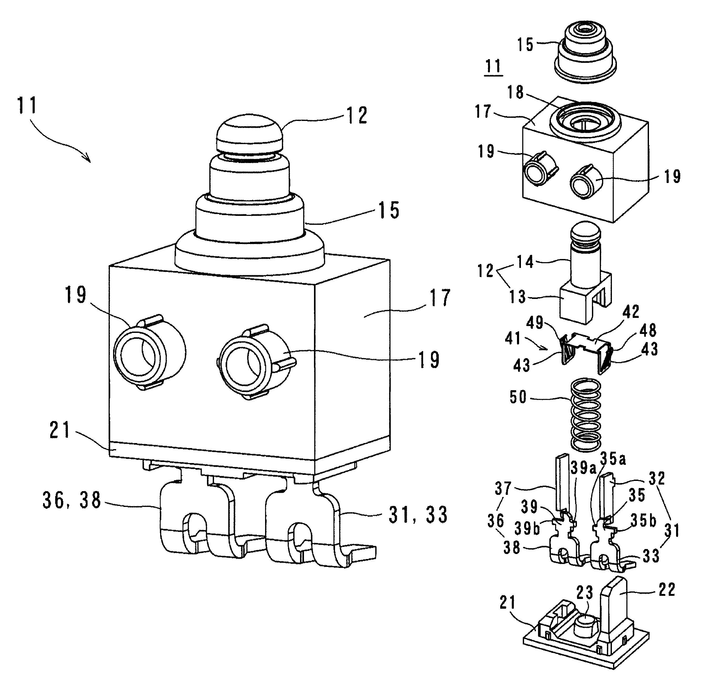
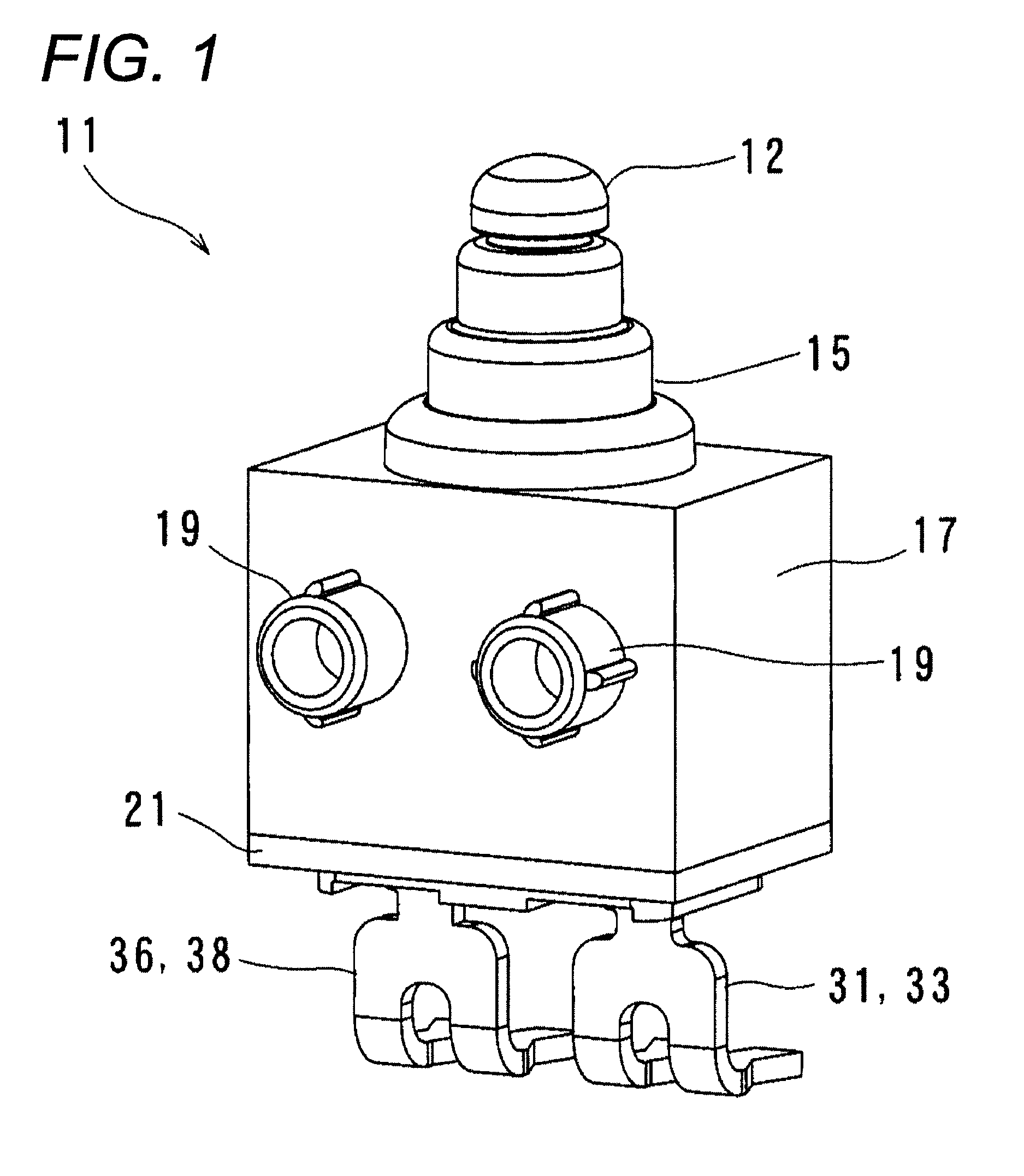
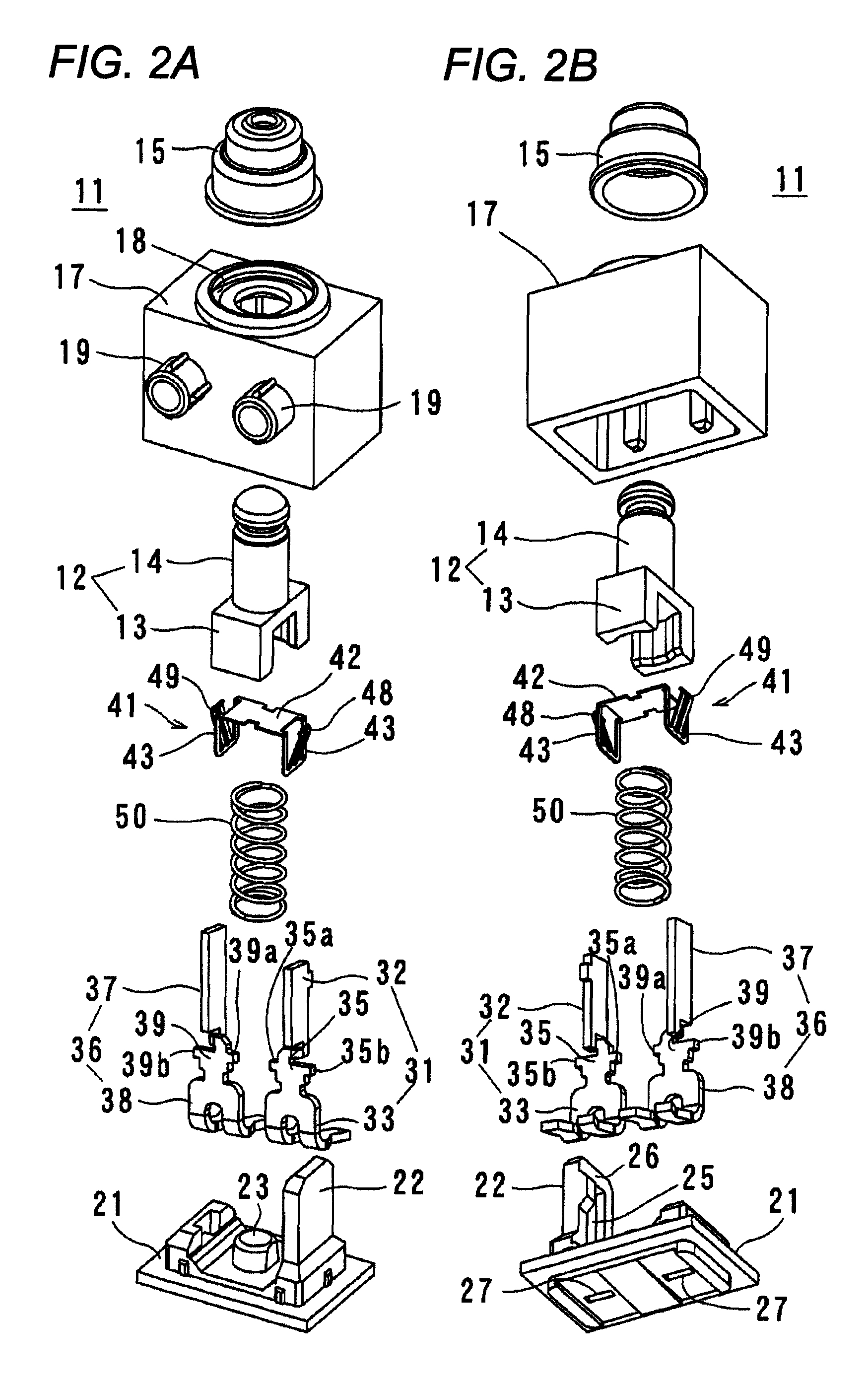
[0039]A switch 11 provided with terminals 33, 38 according to a first embodiment includes a push button 12, a casing (housing) 17, a base 21, a first fixing terminal 31, a second fixing terminal 36, and a slider 41 as shown in FIGS. 1, 2A, and 2B.

[0040]The push button 12 has a seat 13 in which a recessed portion is formed, and a cylindrical pressed section 14 extending upward from the seat 13 in the axial direction. The push button 12 is arranged inside the casing (housing) 17 movably in the axial direction orthogonal to the base 21, and an upper end of the pressed section 14 protrudes upward from the casing (housing) 17 through a cylindrical cap 15. Therefore, the pressed section 14 is pressed from an exterior, so that the push button 12 is moved in the axial direction.

[0041]The housing 17 is formed in a box shape in which a bottom portion is opened, and has an annular groove 18 formed on an upper surface thereof, the annular groove through which the pressed section 14 of the push ...

second embodiment

[0061]In the first embodiment, the first externally connecting terminal section 33 and the second externally connecting terminal section 38 are bent in the opposite direction to the protruding direction of the positioning projection sections 19 of the housing 17. However, the present invention is not limited to this. For example, as in a switch 70 according to a second embodiment shown in FIG. 11, a base 21 to which a first externally connecting terminal section 33 and a second externally connecting terminal section 38 are insert-molded is rotated by 180° and installed in a housing 17. Thereby, the first externally connecting terminal section 33 and the second externally connecting terminal section 38 are bent in the same direction as the protruding direction of positioning projection sections 19. Apart from this point, the second embodiment is the same as the first embodiment. Thus, the same parts will be given the same reference numerals and description thereof will not be repeate...


PUM


Abstract

The present invention is to provide a terminal capable of being reduced in size and a connecting holder of the same. The terminals protrude from a housing, and include a branch portion, a terminal section cut out from the branch portion toward a tip end of the terminal section in a longitudinal direction, and a bent portion adjacent to the tip end. By decreasing a distance from the bent portion to a tip end of the terminal, variations in length size to the tip end due to bending can be suppressed.

Description

BACKGROUND OF THE INVENTION[0001]1. Technical Field[0002]The present invention relates to a terminal used for an electronic device, particularly switchgear such as a relay and a switch, and a connection structure of the same.[0003]2. Related Art[0004]Conventionally, a terminal used for a switch and the like, for example, DE 10,061,112 A1 describes a terminal in which an insulation displacement terminal is used as an externally connecting terminal and a terminal on the side of a connecting holder passes through the insulation displacement terminal, so that the switch can be operated.[0005]However, in the above terminal, in order to enhance contact reliability between the insulation displacement terminal and the terminal on the side of the connecting holder, a surface area of the insulation displacement terminal is increased. Therefore, the insulation displacement terminal runs over an outer surface of an electronic device, and there is a problem that the electronic device cannot be r...

Claims


Application Information

Patent Timeline
Patent Type & Authority Patents(United States)
IPC IPC(8): H01R13/04H01H1/58H01R13/11H01H13/52H01R12/71H01R13/26H01R13/64H01H1/40H01H1/36
CPCH01R13/04H01H1/5866H01R13/112H01H1/365H01H1/40H01H13/52H01R12/716H01R13/26H01R13/64
Inventor FUJITA, HIROYUKIYONEHARA, HIROTO
Owner ORMON CORP
Why Eureka
Try Eureka