
Secure fluids transfer system for medical use

a fluid transfer system and secure technology, applied in the direction of tube connectors, catheters, etc., can solve the problems of user error detection, high cost, and time-consuming to assemble these fluid transfer systems, and achieve the effect of low cost and simple design and operation

Inactive Publication Date: 2015-10-06
TECHNOFLEX SA
View PDF5 Cites 15 Cited by
  • Summary
  • Abstract
  • Description
  • Claims
  • Application Information

AI Technical Summary

Benefits of technology

The patent describes a locking system for Luer male and female connectors that reduces pressure on the sealing space during fluid transfer to prevent contamination and leakage. The system includes conical male and female surfaces that fit together to form a secure connection. The connectors have a collar that fits into a surrounding collar to prevent any transfer of fluid. The connectors have some play in the initial joining assembly to make engaging the screw easier for users, but the play is reduced at the end of the screw phase to prevent any transfer. The female connector may also have gripping elements for easy handling. The main body of the female connector has a lateral opening that allows fluids to communicate between the internal and external surfaces of the connectors to prevent any loss of fluids during transfer.

Problems solved by technology

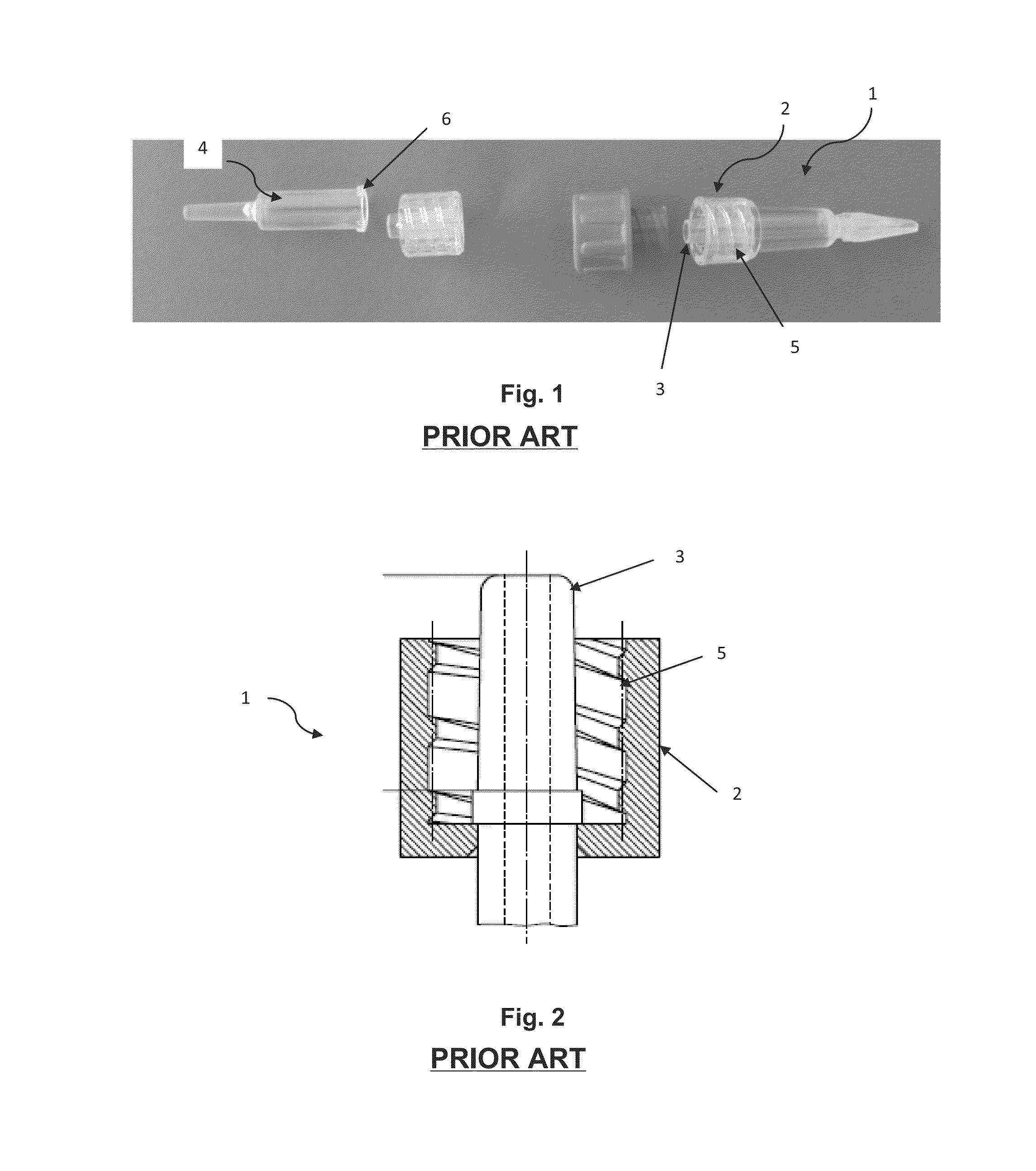
While these Luer connectors 1, 4 are easy to use, handling errors by users have been observed during the coupling action in a large number of Luer connectors.
In particular, where handling is required in aphaeresis, there is a risk of inverting the two lines, for example anticoagulants and saline solution, when the lines both have identical Luer connectors.
Moreover, fluids transfer systems recognized as state of the art that prevent improper connections are generally complex structures comprised of a large number of initially distinct parts.
It takes a lot of time to assemble these fluid transfer systems and they are costly.

Method used


Image

  • Secure fluids transfer system for medical use
  • Secure fluids transfer system for medical use
  • Secure fluids transfer system for medical use

Examples


third embodiment

[0098]FIG. 10 shows a partial view of the fluids transfer system for medical use in the invention. The fluids transfer system in FIG. 10 differs from that described in FIGS. 3 to 6 in that the Luer male connector 10 with an internal wall containing an orifice 22 in its internal longitudinal opening has a truncated portion 23 located at the end of the internal longitudinal opening that has the said second threading 20, and the end of the main body of the Luer female connector 11 is conical 34 so that with this end being located near the orifice 22, 23 of the said internal wall, fluids are directed through the orifice. Advantageously, no fluid retention is observed with this fluids directional system.

[0099]These conical parts 23, 34 are kept away from contact with each other in order to avoid dual alignment.

fourth embodiment

[0100]FIG. 11 shows a partial view of the fluids transfer system for medical use in the invention. The fluids transfer system in FIG. 11 differs from that described in FIGS. 3 to 6 in that the Luer male connector 10 with an internal wall containing an orifice 22 in its internal longitudinal opening and this orifice has a portion 35 protruding from the said wall being located at the end of the internal longitudinal opening that has the before-mentioned second threading 20. This protruding portion 35, here for illustrative purposes a portion of a tube, has an external diameter inferior to the diameter of the internal channel 15 of the main body of the Luer female connector 11 so formed that it can be received in the internal channel 15 when the said Luer male 10 and female 11 connectors are joined so as to direct fluids through the said orifice 22.

[0101]This protruding part 35 and the wall of the main body of the Luer female connector delineating the internal channel 15 are kept away ...


PUM


Abstract

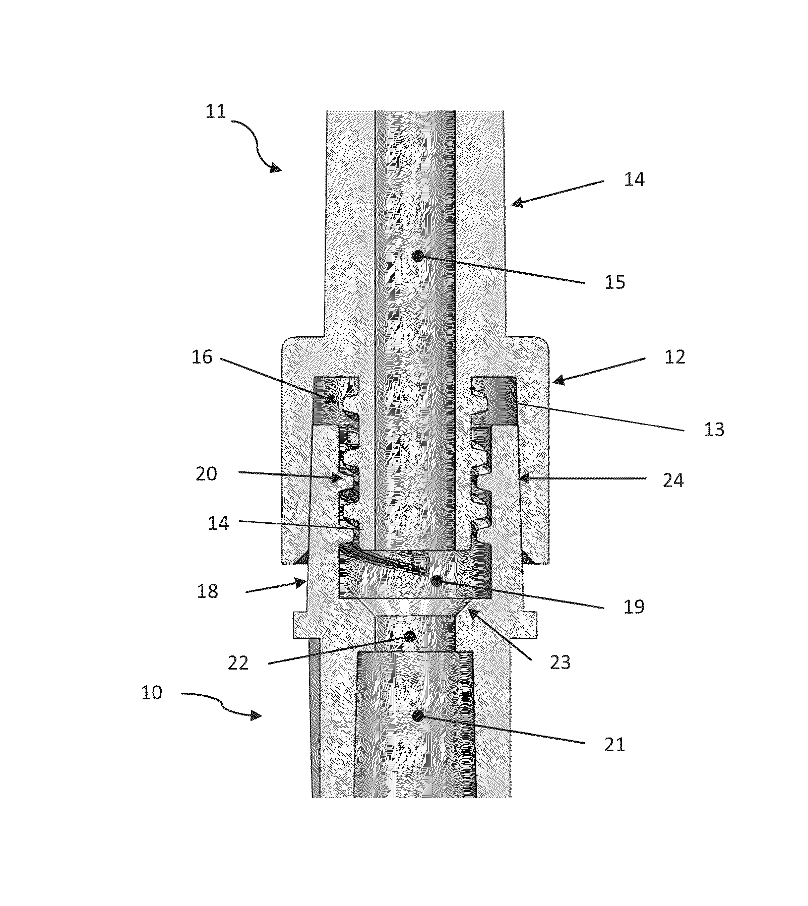
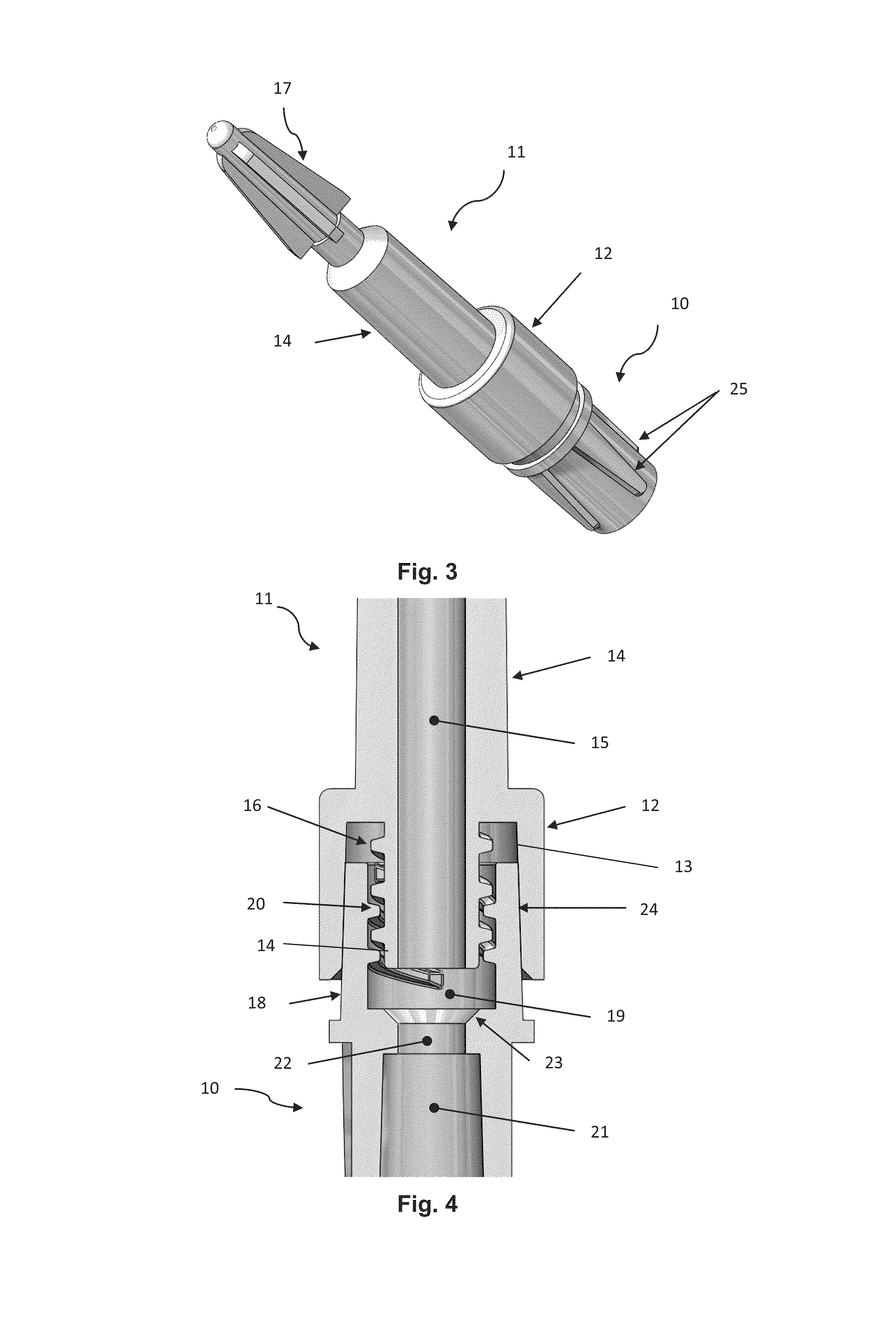
A fluid transfer system includes a Luer female connector having a main body containing an internal channel for passage of fluids and a collar surrounding at least a part of the end of the main body, and a Luer male connector having a main body with a longitudinal internal opening. The main body of the female connector contains a first threading on at least a part of the external surface of that portion that is surrounded by the collar, located at least in part facing an internal surface of the collar; one of the ends of the main body of the Luer male connector contains a second threading on at least a part of its internal surface delineating the longitudinal internal opening, which engages into and fits in the first threading to ensure joining between the Luer male and female connectors.

Description

BACKGROUND OF THE INVENTION[0001]1. Domain of the Invention[0002]This invention is in the field of Luer connections, specifically a secure mechanism for the transfer of medical use solutions.[0003]2. Technological Background[0004]It is a well-known practice to use Luer connections to connect for example medical devices to each other for introducing medical solutions from a primary recipient to ducts within human bodies.[0005]FIGS. 1 and 2 show state of the art Luer male and female connectors. A Luer male connector 1 comprises a collar 2 encircling at least a part of the conical male part 3 whose external surface joins to the female conical connecting surface of the Luer female connector 4 when these Luer male 1 and female 4 connectors are joined together.[0006]The collar 2 of the Luer male connector 3 features an internal threading 5 whereas the Luer female connector 4 contains the largest of the rims 6 that fit to the internal threading 5 of the collar 2 of the Luer male connector ...

Claims


Application Information

Patent Timeline
Patent Type & Authority Patents(United States)
IPC IPC(8): A61M39/10
CPCA61M39/10A61M2039/1038A61M2039/1027A61M2039/1033A61M2039/1094
Inventor BONNET, FREDERICCAPITAINE, FRANCOIS
Owner TECHNOFLEX SA
Learn More