
Modified heat chamber and method to improve heat cycle efficiency using airflow control

a heat chamber and airflow control technology, applied in the direction of machines/engines, baking ovens, light and heating apparatus, etc., can solve the problems of affecting the air flow within the heat chamber, and achieve the effect of reducing the required processing time and energy cost, reducing the time and cost required, and reducing the area with temperature variations or hot and cold spots

Inactive Publication Date: 2015-09-29
LAFFLER DONALD L +1
View PDF5 Cites 1 Cited by
  • Summary
  • Abstract
  • Description
  • Claims
  • Application Information

AI Technical Summary

Benefits of technology

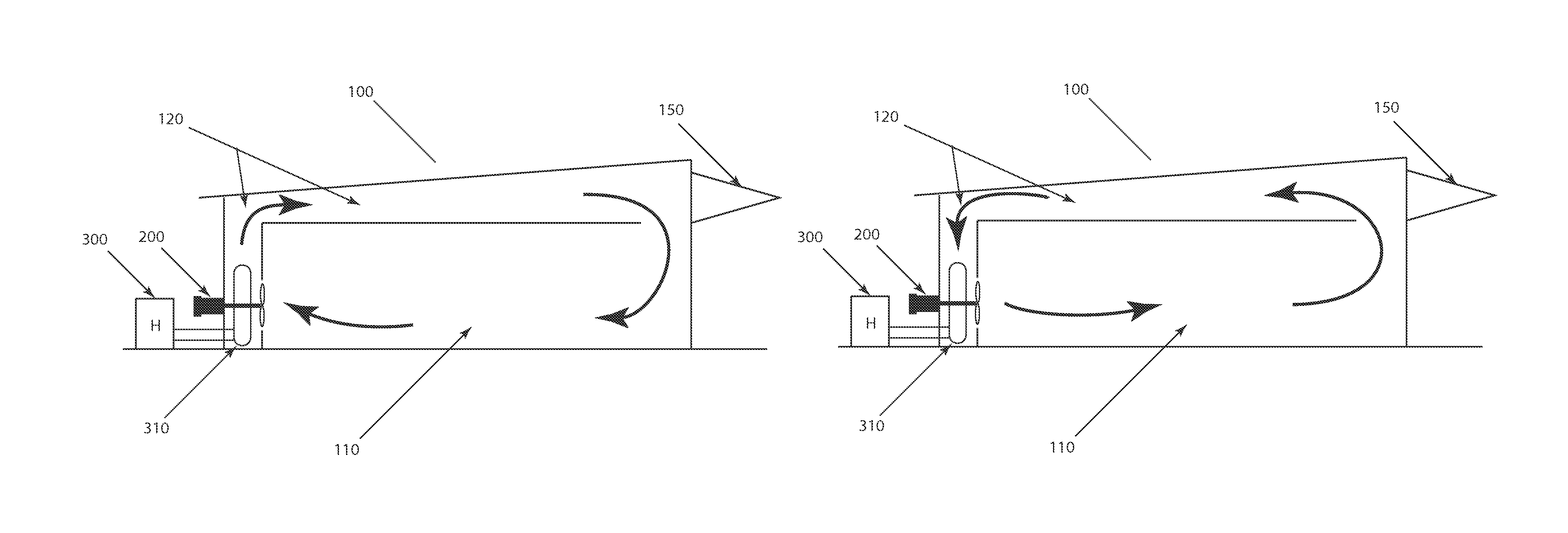
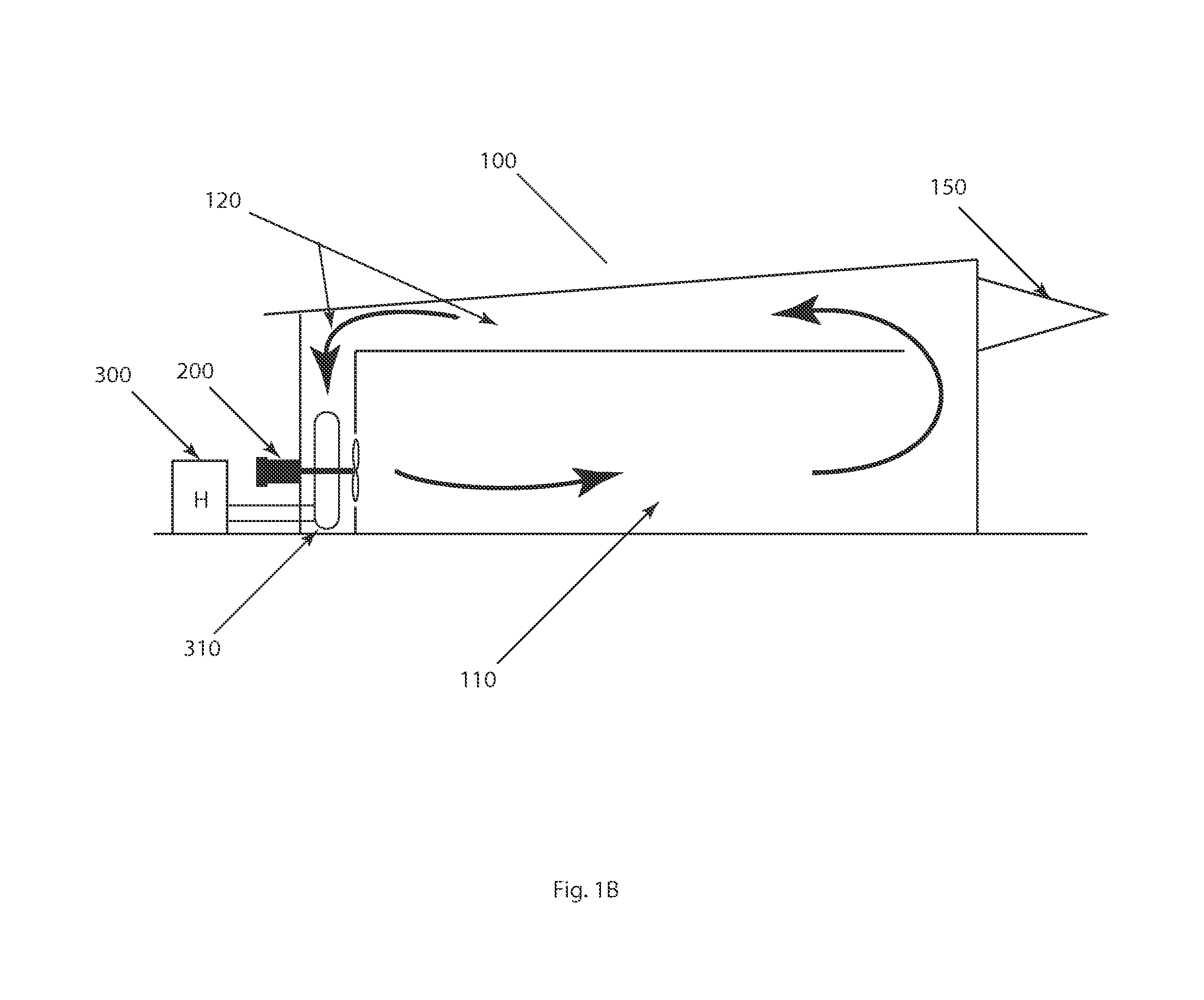
The present invention is a modified heat chamber that reduces heating time and energy costs by programming the control mechanism to achieve uniform temperature distribution. The high volume airflow with reversed airflow direction improves air mixing and reduces temperature variations. The load configuration affects the airflow, and the fan direction reversal moves the low pressure areas around the product load to different areas surrounding it. The improved heating chamber increases production rates and reduces process costs. It is based on sound thermodynamic principles and can heat various amounts of materials to a near uniform temperature.

Problems solved by technology

In addition, air flow within the heat chamber is affected by the product load and load configuration, each unique load creates different low pressure pockets or dead spots where the heated air does not effectively circulate.

Method used


Image

  • Modified heat chamber and method to improve heat cycle efficiency using airflow control
  • Modified heat chamber and method to improve heat cycle efficiency using airflow control
  • Modified heat chamber and method to improve heat cycle efficiency using airflow control

Examples


Embodiment Construction

[0024]For the purposes of promoting an understanding of the principles in accordance with the disclosure, reference will be made to the embodiments illustrated in the drawings and specific language will be used to describe the same. It will nevertheless be understood that no limitation of the scope of the disclosures is thereby intended. Any alterations and further modifications of the inventive features illustrated herein, and any additional applications of the principles of the disclosure as illustrated herein, which would normally occur to one skilled in the relevant art and having possession of this disclosure, are to be considered within the scope of the disclosure.

[0025]As used in this specification and the appended claims, the singular forms “a,”“an,” and “the” include plural referents unless the context clearly dictates otherwise. In describing and claiming the present disclosure, the following terminology will be used in accordance with the definitions set out below. As use...


PUM


Abstract

The present invention relates to improvements in the art of operating large heat chambers so as to reduce both the time and the cost required for heating materials. More specifically, the modified heat chamber of the present invention provides a programmable control mechanism capable of significantly reducing areas with temperature variations or hot and cold spots. A programmable heat chamber leads to significant reductions in the required processing time and in the cost of the required energy.

Description

[0001]This application claims priority to U.S. Provisional Application 61 / 667,995 filed Jul. 4, 2012, the disclosure incorporated by reference.BACKGROUND[0002]Traditional large heat chambers operate by delivering heat energy to materials by one or a combination of radiant heat, hot air convection or hot forced air. The configuration of the heat delivery mechanism is generally fixed by the chamber designer. The chamber users can usually only select heating time and temperature for a specific application. These parameters are determined experimentally by using instrumentation and running test loads of materials. This method is satisfactorily but may not produce as economical process as may be achieved using other methods.[0003]A particular load configuration with a fixed airflow velocity and direction in forced hot air heat chambers often produces uneven heating with hot and cold spots. The hot and cold spots may be a significant issue when a product or process requires achieving a sp...

Claims


Application Information

Patent Timeline
Patent Type & Authority Patents(United States)
IPC IPC(8): H05B6/68F26B21/02F04D27/00F26B21/12A21B1/26
CPCF04D27/007F26B21/026F26B21/12
Inventor LAFFLER, DONALD L.HARDIN, JAMES T.
Owner LAFFLER DONALD L
Learn More