
System and method for displaying a runway position indicator

a technology of a position indicator and a display method, which is applied in the direction of automatic aircraft landing aids, aircraft traffic control, navigation instruments, etc., can solve the problems of discontinuance of landing attempt, poor visibility, and the most difficult task a pilot undertakes, so as to improve the accuracy and safety of approach and landing

Active Publication Date: 2015-09-08
HONEYWELL INT INC
View PDF17 Cites 7 Cited by
  • Summary
  • Abstract
  • Description
  • Claims
  • Application Information

AI Technical Summary

Benefits of technology

The invention is a device that helps pilots land on a runway safely and accurately. It uses a special light to show the pilot where they are supposed to land their plane. This device helps the pilot adjust their flight path and land on the runway, making the approach and landing process easier and safer.

Problems solved by technology

The approach to landing and touch down on the runway of an aircraft is probably the most challenging task a pilot undertakes during normal operation.
An approach outside of this envelope can result in an undesirable positioning of the aircraft with respect to the runway, resulting in possibly discontinuance of the landing attempt.
In some instances visibility may be poor during approach and landing operations, resulting in what is known as instrument flight conditions.

Method used


Image

  • System and method for displaying a runway position indicator
  • System and method for displaying a runway position indicator
  • System and method for displaying a runway position indicator

Examples


Embodiment Construction

[0022]The following detailed description is merely illustrative in nature and is not intended to limit the embodiments of the subject matter or the application and uses of such embodiments. Any implementation described herein as exemplary is not necessarily to be construed as preferred or advantageous over other implementations. Furthermore, there is no intention to be bound by any expressed or implied theory presented in the preceding technical field, background, brief summary, or the following detailed description.

[0023]For simplicity and clarity of illustration, the drawing figures depict the general structure and / or manner of construction of the various embodiments. Descriptions and details of well-known features and techniques may be omitted to avoid unnecessarily obscuring other features. Elements in the drawings figures are not necessarily drawn to scale: the dimensions of some features may be exaggerated relative to other elements to assist improve understanding of the examp...


PUM


Abstract

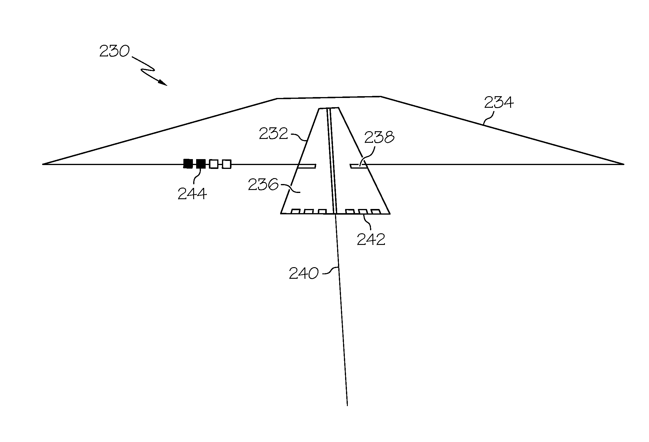
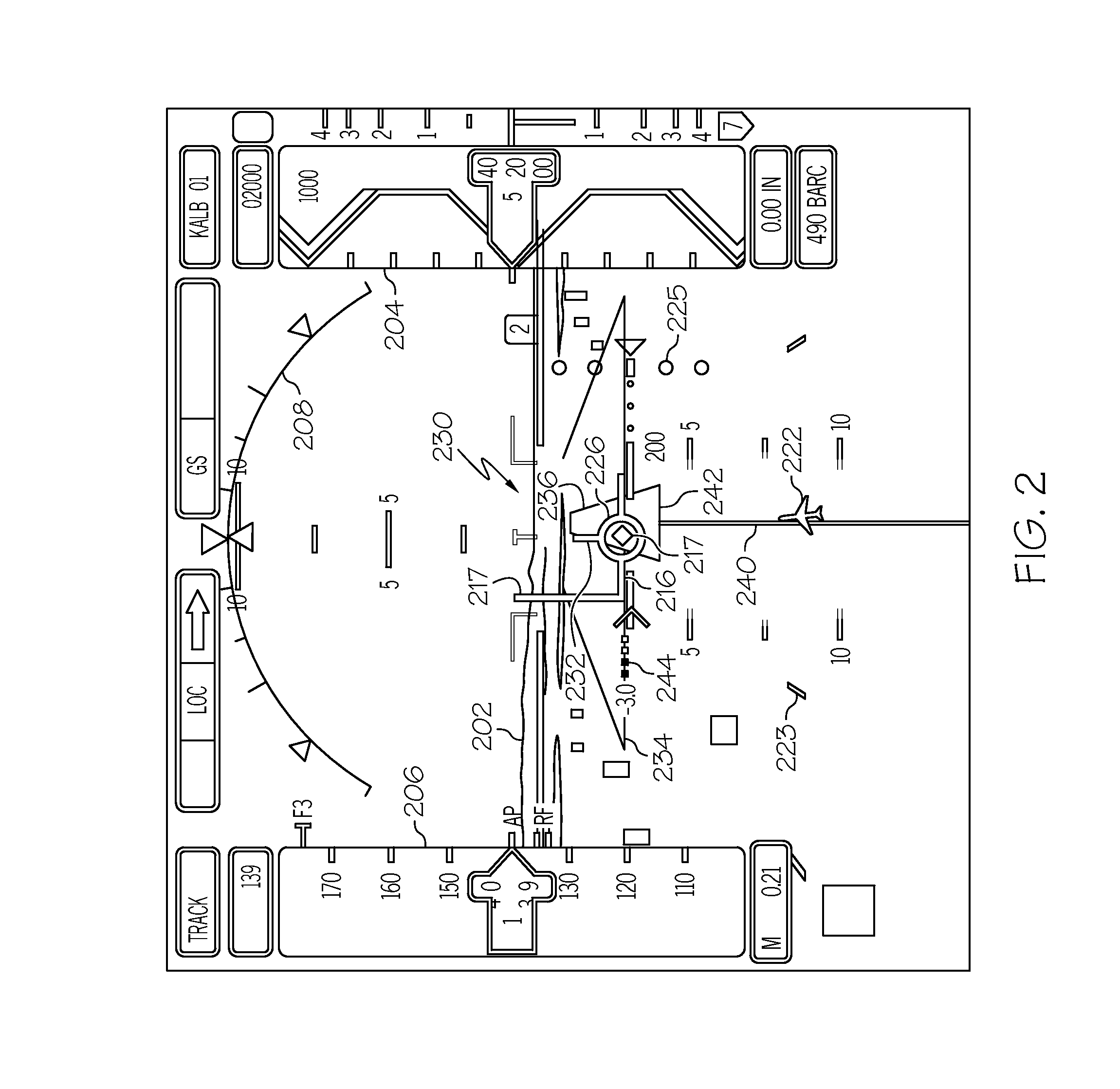
A dynamic runway indicator is displayed overlying a conformal runway for assisting a pilot in completing an approach to landing on a runway. The dynamic runway indicator includes a polygon, that by changing position with respect to the conformal runway, provides advanced instrumentation cues to the pilot for adjusting the aircraft flight path to a normal, or recommended, path to the runway for landing, thereby assisting the pilot to improve the accuracy and safety of the approach and landing.

Description

TECHNICAL FIELD[0001]The present invention generally relates to a system for improving a pilot's ability to complete an approach to a runway and more particularly to a system for displaying information to support a pilot's ability to fly a stabilized approach.BACKGROUND[0002]The approach to landing and touch down on the runway of an aircraft is probably the most challenging task a pilot undertakes during normal operation. To perform the landing properly, the aircraft approaches the runway within an envelope of attitude, course, speed, and rate of descent limits. The course limits include, for example, both lateral limits and glide slope limits. An approach outside of this envelope can result in an undesirable positioning of the aircraft with respect to the runway, resulting in possibly discontinuance of the landing attempt.[0003]In some instances visibility may be poor during approach and landing operations, resulting in what is known as instrument flight conditions. During instrume...

Claims


Application Information

Patent Timeline
Patent Type & Authority Patents(United States)
IPC IPC(8): G01C21/00G08G5/00G08G5/02
CPCG08G5/025G08G5/0047G08G5/0021
Inventor GANNON, AARONWYATT, IVAN SANDYNICHOLS, TROYSUDDRETH, JOHN G.
Owner HONEYWELL INT INC
Learn More