
Apparatus and method for clamping mitered corners

a technology of mitered corners and apparatus, which is applied in the field of apparatus and method for clamping mitered corners, can solve the problems of complex clamping devices that are generally heavy, bulky, and expensive to manufacture, and require specialized equipment that is rather expensiv

Inactive Publication Date: 2015-08-25
OLSON KEVIN
View PDF7 Cites 0 Cited by
  • Summary
  • Abstract
  • Description
  • Claims
  • Application Information

AI Technical Summary

Benefits of technology

The patent is about a kit for clamping a mitered corner, which consists of two frame members. The kit includes a band retaining member and a clamp band for engaging the band retainer and the frame members to exert a compressive force on the mitered corner. The band retainer prevents the clamp band from moving relative to the mitered corner. This invention can help ensure the stability and security of the mitered corner.

Problems solved by technology

Traditional methods used to join mitered corners often require complex clamp devices that are generally heavy, bulky, and expensive to manufacture.
Not only does this involve another operational step to the process of framing, it also requires specialized equipment that is rather expensive.

Method used


Image

  • Apparatus and method for clamping mitered corners
  • Apparatus and method for clamping mitered corners
  • Apparatus and method for clamping mitered corners

Examples


Embodiment Construction

[0032]Before explaining at least one embodiment of the presently disclosed and claimed inventive concept(s) in detail, it is to be understood that the presently disclosed and claimed inventive concept(s) is not limited in its application to the details of construction, experiments, exemplary data, and / or the arrangement of the components set forth in the following description or illustrated in the drawings. The presently disclosed and claimed inventive concept(s) is / are capable of other embodiments or of being practiced or carried out in various ways. Also, it is to be understood that the phraseology and terminology employed herein is for the purpose of description and should not be regarded as limiting.

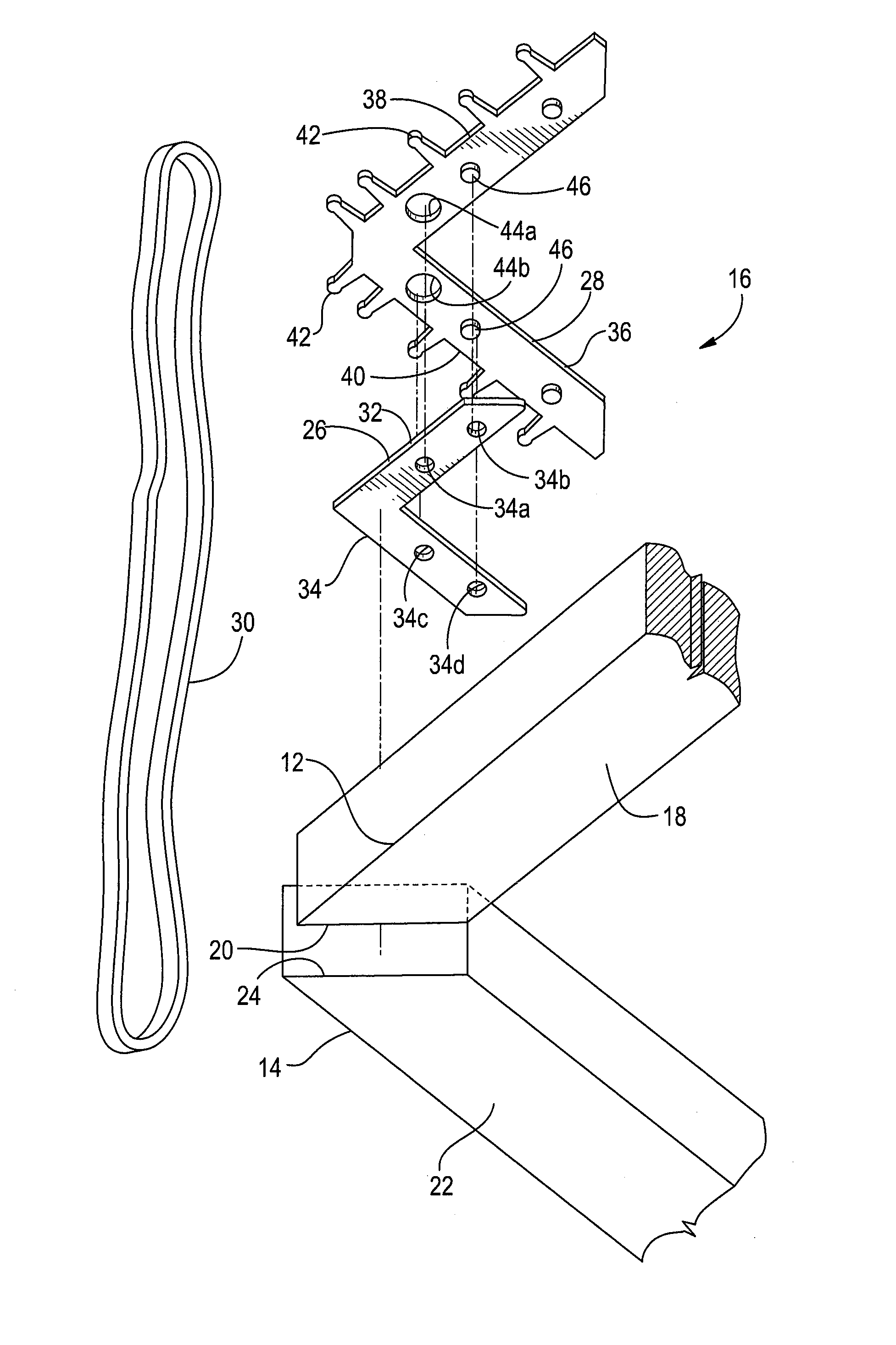
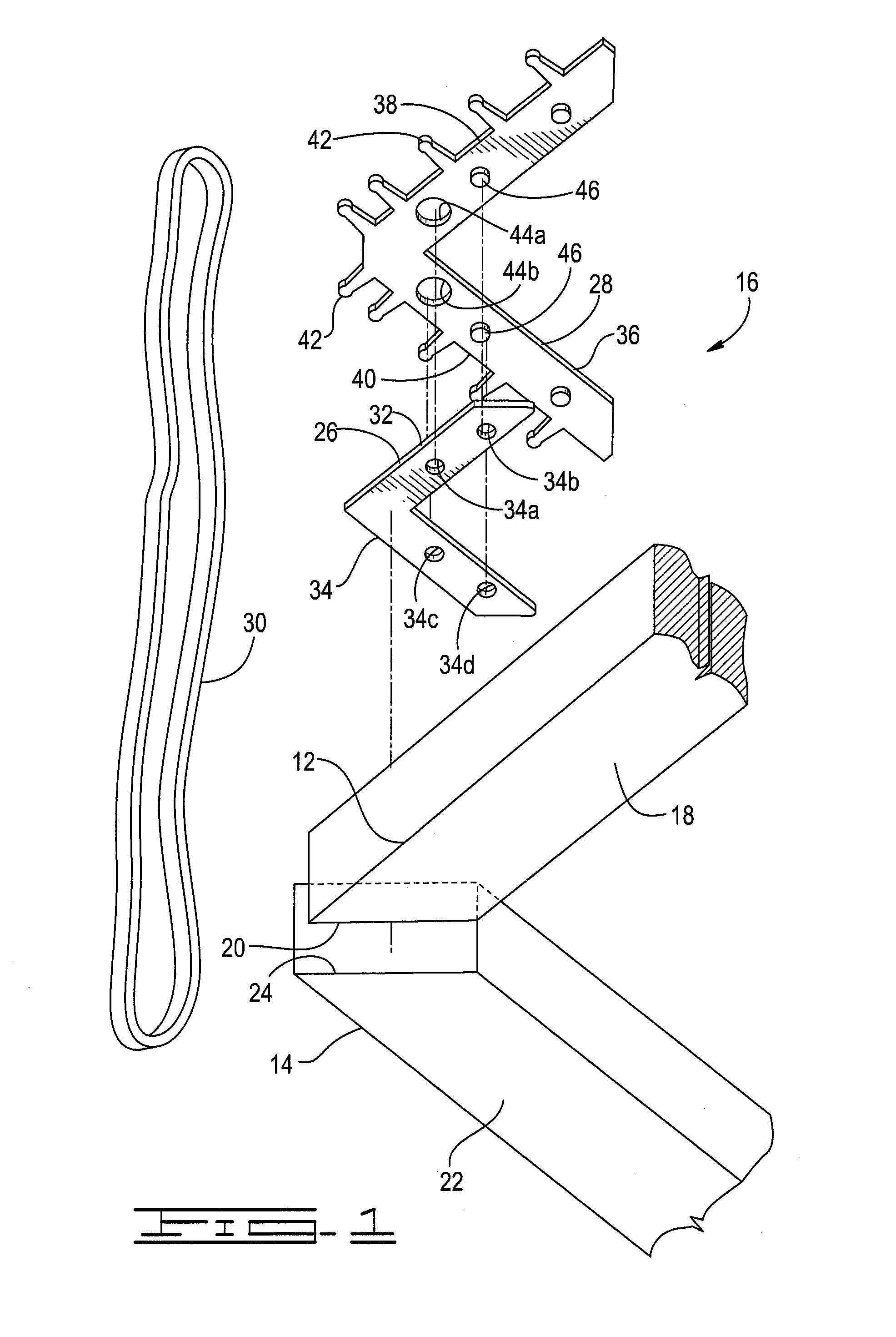
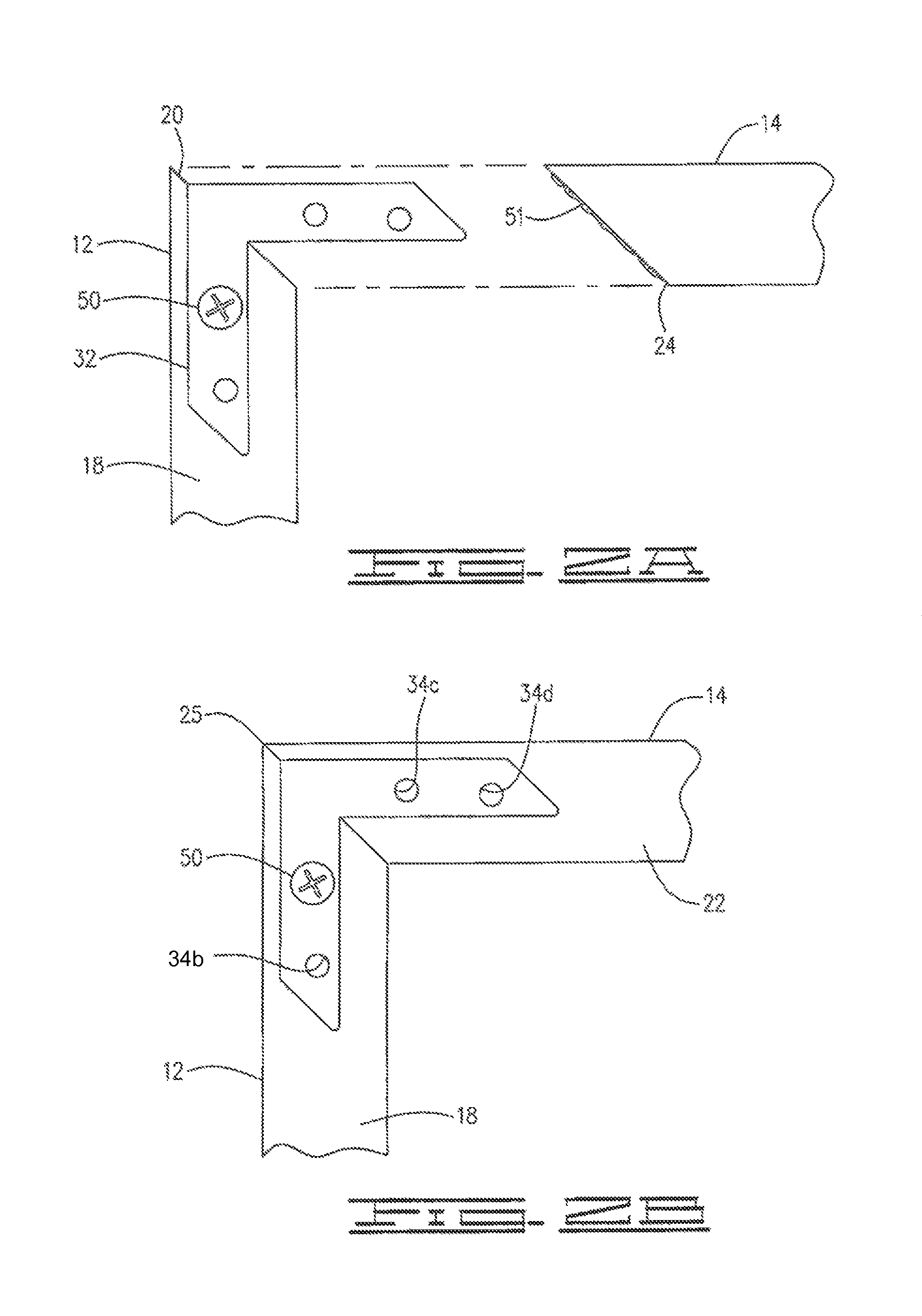
[0033]Referring now to the drawings, FIG. 1 illustrates two mitered frame members 12 and 14, and a clamp kit 16 constructed in accordance with the inventive concepts disclosed herein. The first mitered frame member 12 has a front surface 18, an opposing back surface, and a pair of mi...


PUM


Abstract

A kit for clamping and joining a miter joint between a first frame member and a second frame member comprising a band retaining member and a clamp band. The band retaining member has a base portion that is adapted to be positioned and attached adjacent the first and second frame members when the first and second frame members are together to form the mitered corner. The band retaining member has at least one band retainer extending from the base portion. The clamp band is wrapped around the first and second mitered frame members and about the at least one band retainer of the band retaining member in such a way that the clamp band is held in position while it extends across the mitered corner so as to exert a compressive force in a direction substantially perpendicular to the joint of the mitered corner.

Description

CROSS REFERENCE TO RELATED APPLICATIONS[0001]This application is a conversion of U.S. Provisional Patent Application Ser. No. 61 / 409,031, filed Nov. 1, 2010, the contents of which are hereby incorporated by reference in its entirety.STATEMENT REGARDING FEDERALLY SPONSORED RESEARCH OR DEVELOPMENT[0002]Not applicable.BACKGROUND OF THE INVENTION[0003]1. Field of the Invention[0004]The present invention disclosed herein relates to clamps, and more particularly, but not by way of limitation, to an apparatus and method for clamping mitered corners (or miter joints).[0005]2. Brief Description of Related Art[0006]In fabricating picture frames and the like, in which the ends of adjacent frame members are mitered to form corners, it is generally desirable to minimize or entirely avoid making marks on the portions of the frame that are in view when the frame is hung on a wall. Thus, the mitered corners in many such assemblies are fastened with glue rather than with nails, which must be driven ...

Claims


Application Information

Patent Timeline
IPC IPC(8): B25B5/00
CPCB25B5/00B25B5/142B25B5/163
Inventor OLSON, KEVIN
Owner OLSON KEVIN
Learn More