
Apparatus and method for monitoring and controlling detection of stray voltage anomalies

a technology of stray voltage and apparatus, which is applied in the direction of frequency selective voltage/current level measurement, instruments, alarms, etc., can solve the problems of unsatisfactory or dangerous anomalies, obvious dangers to people and animals in the general public, and the presence of “stray voltages” in the system

Active Publication Date: 2015-08-18
OSMOSE UTILITIES SERVICES
View PDF57 Cites 1 Cited by
  • Summary
  • Abstract
  • Description
  • Claims
  • Application Information

AI Technical Summary

Benefits of technology

This patent describes an apparatus and methods for detecting stray voltage anomalies in electrical fields. The apparatus includes a sensor probe with an electrode that detects the electrical field and a processor that analyzes the data from the sensor probe to identify voltage anomalies in the field. An indicator alerts the user to the presence of the voltage anomaly. The technical effect is the ability to detect and locate voltage anomalies in electrical fields, which can help to improve safety and prevent damage or injury.

Problems solved by technology

Large power distribution systems, especially those in large metropolitan areas, are subject to many stresses, which may occasionally result in the generation of undesirable or dangerous anomalies.
An infrequent, but recurrent problem in power distribution infrastructures is the presence of “stray voltages” in the system.
These energized objects present obvious dangers to people and animals in the general public.
Detecting the existence of stray voltages by means of assessing electromagnetic radiation is not practical because the wavelength of a 60 Hz electromagnetic wave is approximately 5,000 kilometers (i.e., about 3,107 miles) in length.
Due to power distribution networks typically having many miles of buried cable carrying perhaps thousands of amperes of current, the magnetic field in any one location due to such normal load is likely to be very high.
Detecting magnetic fields arising from a relatively weak stray voltage anomaly would be very difficult due to the interference from strong ambient magnetic fields arising from normal loads and, therefore, it has been determined that the best way to detect a stray voltage anomaly is to assess the electric field.
However, inspectors using these detection devices are typically required to make contact with portions of electrical infrastructures, such as streetlamp bases or manhole covers, in order to obtain accurate measurements for determining the existence of potentially dangerous stray voltages.
These manual inspections are undoubtedly time-consuming and give a false sense of security.

Method used


Image

  • Apparatus and method for monitoring and controlling detection of stray voltage anomalies
  • Apparatus and method for monitoring and controlling detection of stray voltage anomalies
  • Apparatus and method for monitoring and controlling detection of stray voltage anomalies

Examples


Embodiment Construction

[0036]Embodiments of the present invention generally relate to apparatus and methods for detecting a stray voltage anomaly in an electric field. For purposes of clarity, and not by way of limitation, illustrative depictions of the present invention are described with references made to the above-identified drawing figures. Various modifications obvious to one skilled in the art are deemed to be within the spirit and scope of the present invention.

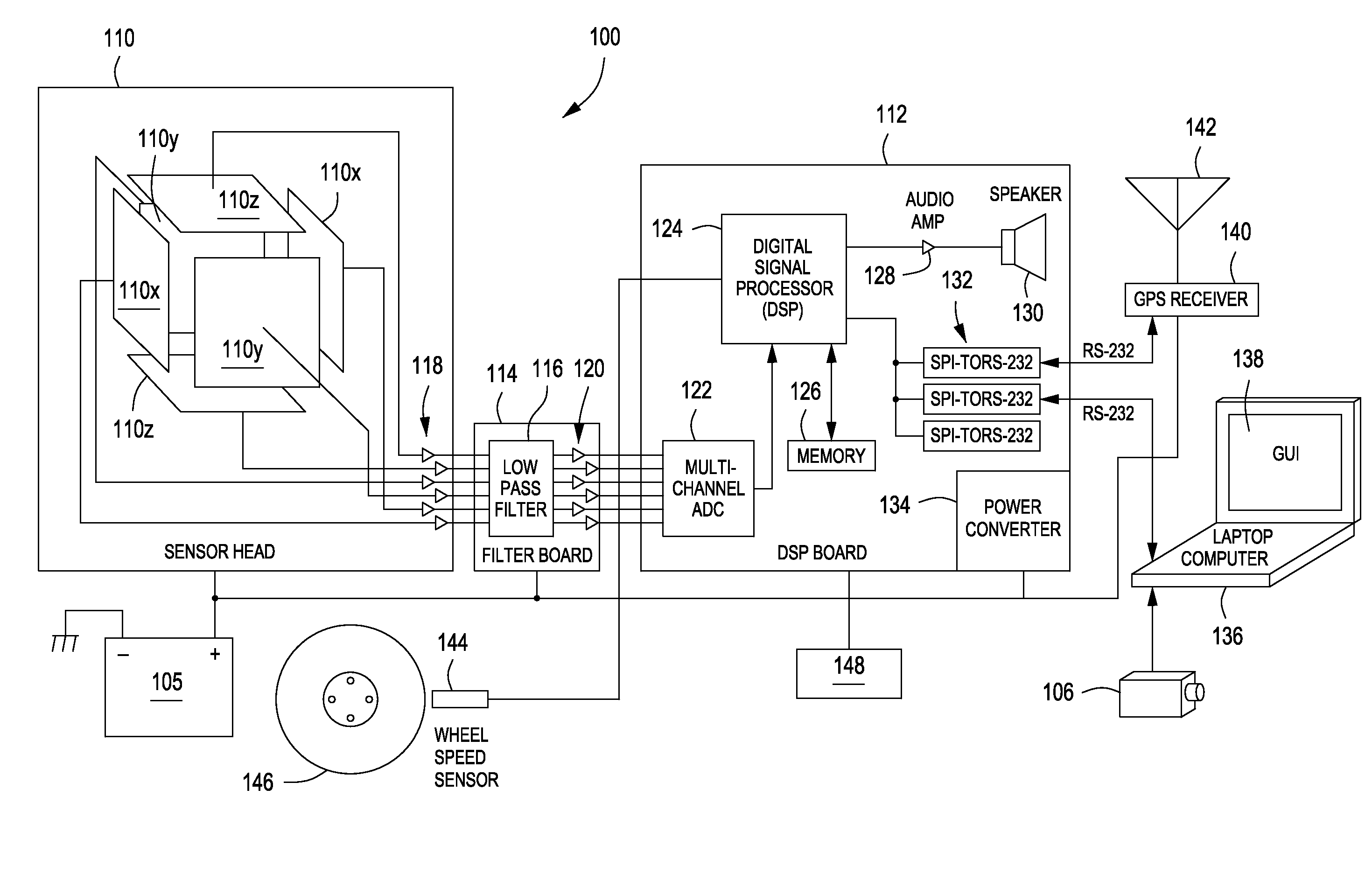
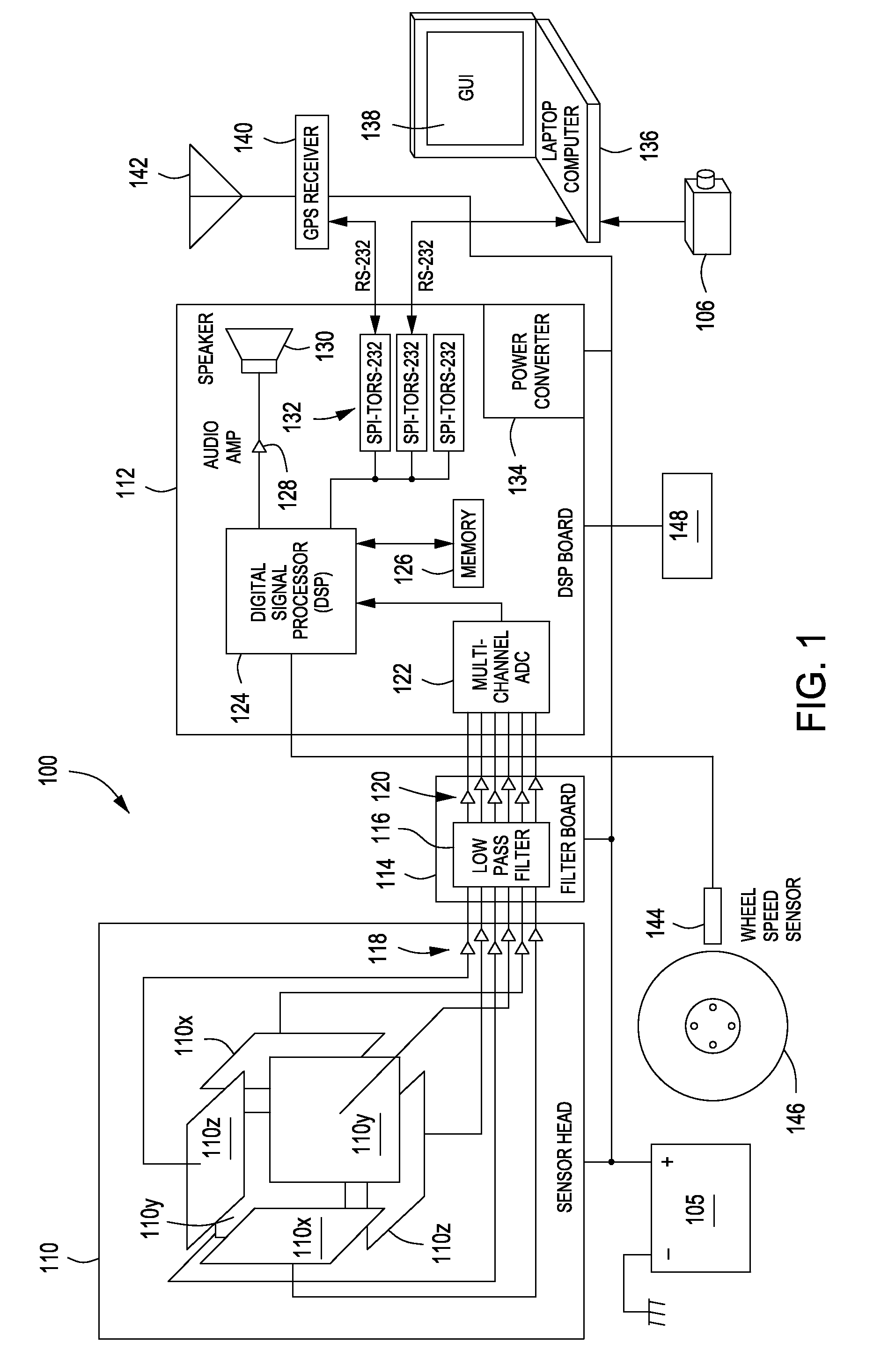
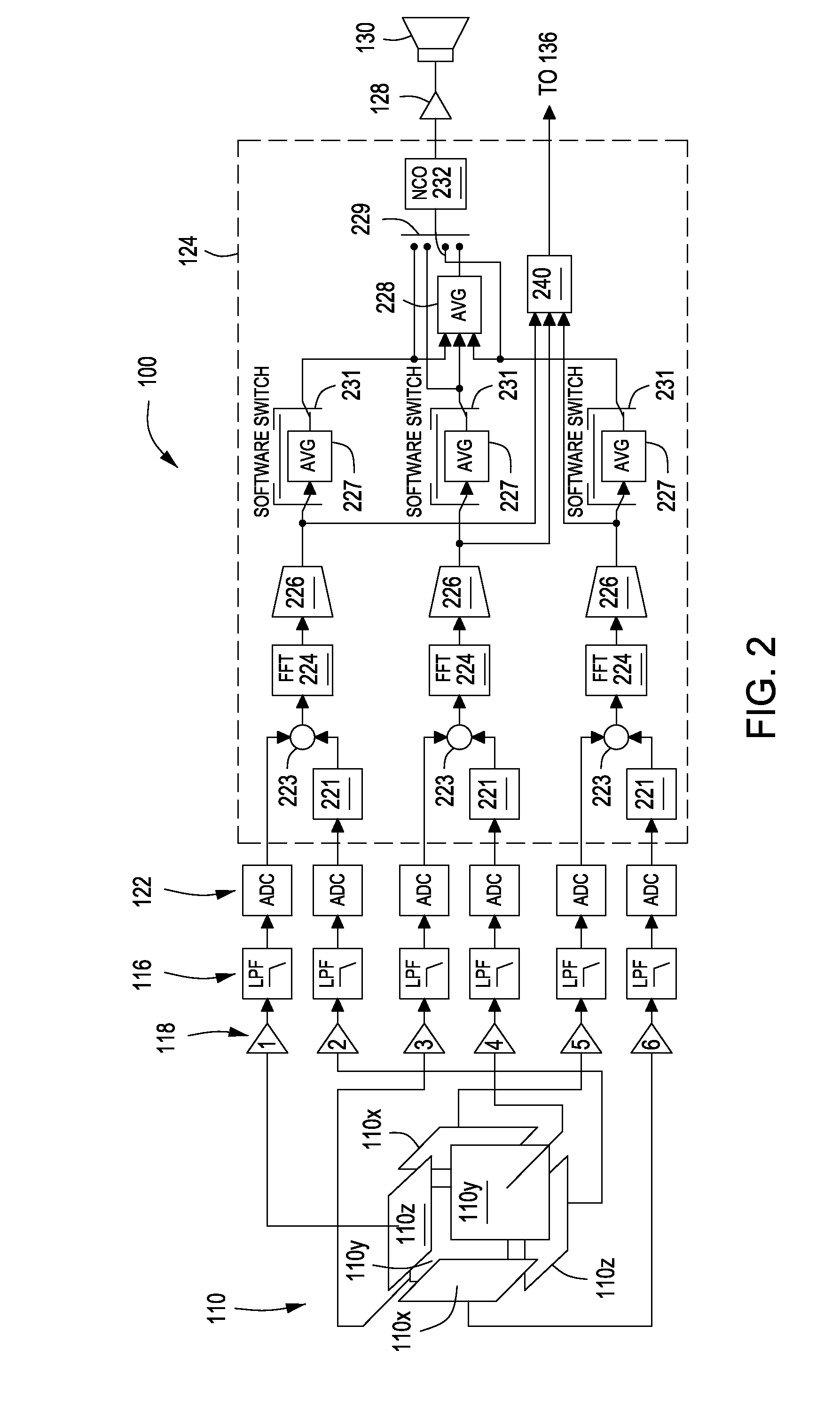
[0037]FIG. 1 is a schematic diagram of an exemplary sensor system in accordance with some embodiments of the present invention. FIGS. 2-2A are schematic diagrams illustrating the operation of the sensor system employing digital electronic processing in accordance with some embodiments of the present invention. To best understand the invention the reader should refer to FIGS. 1, 2 and 2A simultaneously.

[0038]In accordance with some embodiments of the present invention, sensor system 100 generally comprises a detection system unit (DSU) 110, ...


PUM


Abstract

Apparatus and methods for detecting stray voltage anomalies in electric fields are provided herein. In some embodiments, an apparatus for detecting an electrical field may comprise: at least one sensor probe for generating data corresponding to an electrical field detected by the at least one sensor probe, wherein the at least one sensor probe comprises at least one electrode; a processor, coupled to the at least one sensor probe, for analyzing the data to identify a voltage anomaly in the electric field; and an indicator, coupled to the processor, for alerting a user to a presence of the voltage anomaly in the electric field.

Description

CROSS-REFERENCE TO RELATED APPLICATIONS[0001]This application is a continuation of pending U.S. patent application Ser. No. 12 / 321,484 filed on Jan. 21, 2009, which is a continuation-in-part of U.S. patent application Ser. No. 11 / 551,222, filed Oct. 19, 2006, now U.S. Pat. No. 7,486,081 which issued on Feb. 3, 2009, which claims benefit of U.S. Provisional Patent Application No. 60 / 728,168, filed Oct. 19, 2005, which is a continuation-in-part of U.S. patent application Ser. No. 11 / 224,909, filed Sep. 13, 2005, now U.S. Pat. No. 7,248,054 which issued on Jul. 24, 2007, which claims benefit of U.S. Provisional Patent Application No. 60 / 639,054, filed Dec. 23, 2004 and U.S. Provisional Patent Application No. 60 / 641,470, filed Jan. 5, 2005. Each of the aforementioned related patent applications is herein incorporated by reference.BACKGROUND[0002]1. Field[0003]The present invention relates to the detection of electric fields, and more particularly, to apparatus and methods of detecting s...

Claims


Application Information

Patent Timeline
Patent Type & Authority Patents(United States)
IPC IPC(8): G01R31/02G01R29/08G01R19/155
CPCG01R31/02G01R29/0814G01R19/155G01C7/04G01R19/0007G01R29/12G08B21/182
Inventor KALOKITIS, DAVIDSCHULTZ, LEONARD JOSHUAPOLYZOIS, CHRISTOS ALKIVIADISPARAGANO, VINCENT
Owner OSMOSE UTILITIES SERVICES
Learn More