
Device for the treatment of biological fluid

a biological fluid and device technology, applied in the field of biological fluid devices, can solve the problems of increased renal insufficiency, large volume of fluid resuscitation, lung failure, etc., and achieve the effect of improving adhesion and prolonging durability

Active Publication Date: 2015-08-04
NOVALUNG
View PDF20 Cites 1 Cited by
  • Summary
  • Abstract
  • Description
  • Claims
  • Application Information

AI Technical Summary

Benefits of technology

The invention is a device that allows for the separation and transfer of molecules or components between two biological fluids. The device includes a membrane chamber with three separate chambers located inside the first chamber. This configuration maximizes the separating surface between the chambers, allowing for efficient transfer of molecules or components. The membrane can be coated with substances like heparin or albumin to prevent the accumulation of substances from the used media on the membrane and maintain its gas permeability over time. The invention can be used for treating biological fluids in medicine, providing a long-term solution for gas transfer.

Problems solved by technology

Patients who must be treated with artificial lung-assist procedure often also suffer from additional renal insufficiency.
Diseases that can lead to lung failure, may require large volumes of fluid resuscitation, and patients often receive significant amounts of blood products.
The resulting physical overload with fluids may possibly lead to a general deterioration of the patient's condition, to pulmonary oedema or even complete organ failure.
This leads however to a complicated constellation of treatment devices and greater stress on the vascular system of the patient.

Method used


Image

  • Device for the treatment of biological fluid
  • Device for the treatment of biological fluid
  • Device for the treatment of biological fluid

Examples


Embodiment Construction

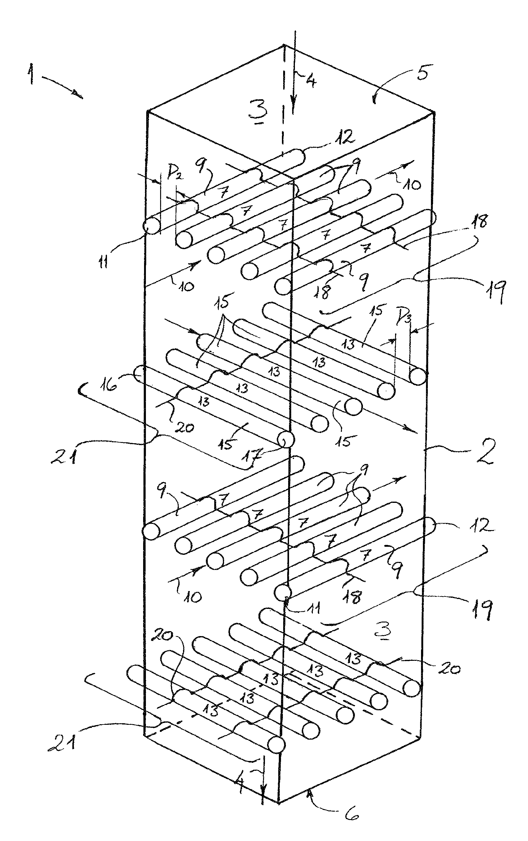
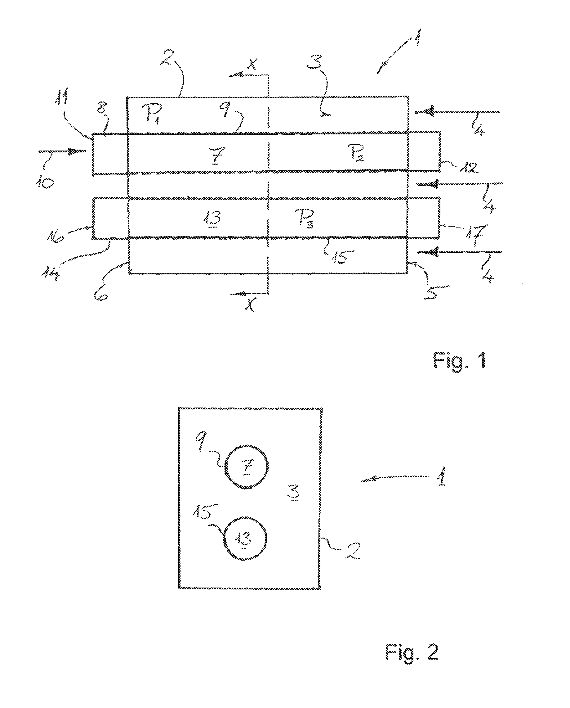
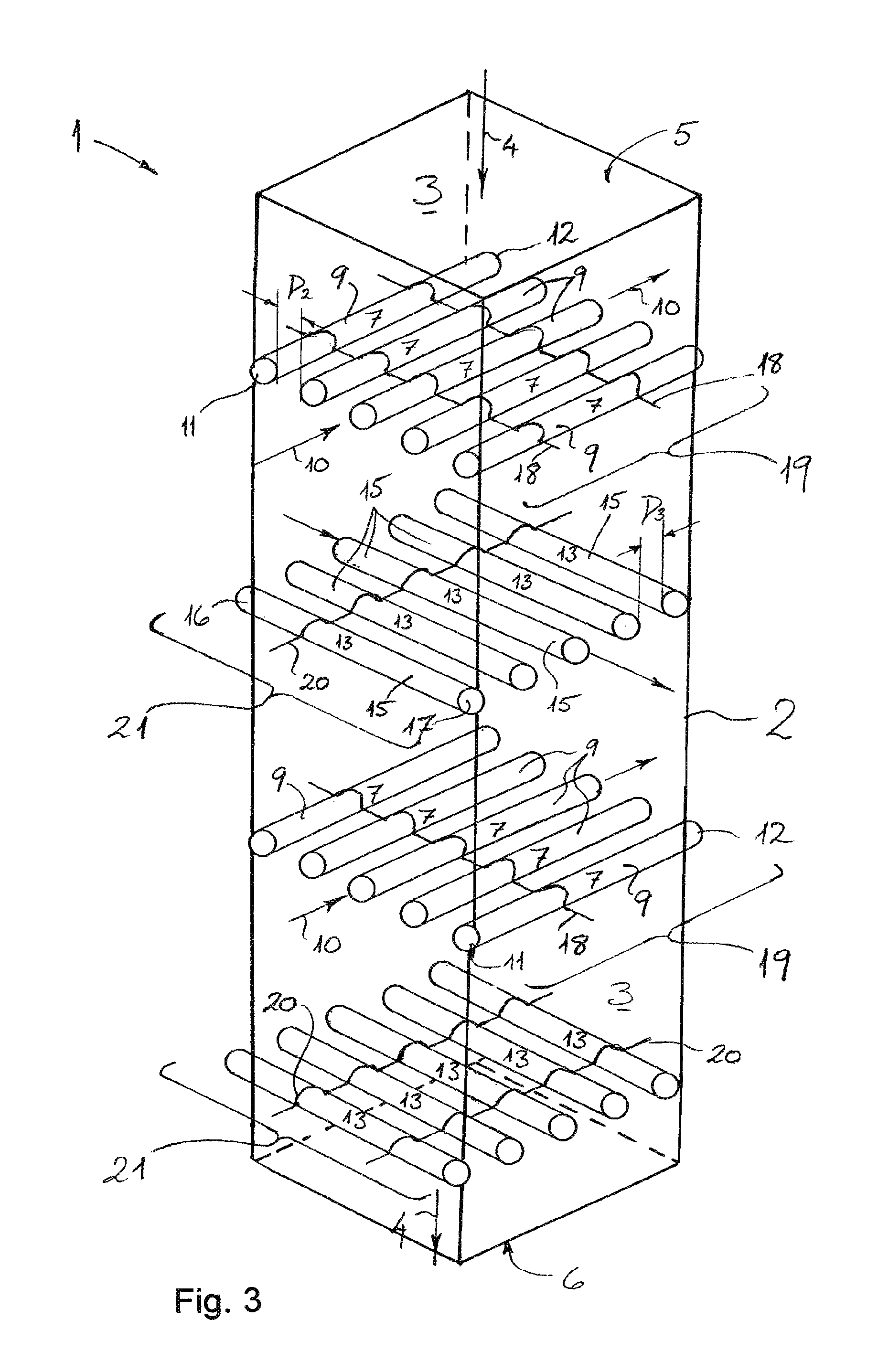
[0044]In FIGS. 1 and 2 a simple representative example of the inventive concept is shown. A device 1 according to the invention includes a housing 2 which encloses or partially defines a first chamber 3. The first chamber 3 is suitable for receiving a biological fluid (as e.g. blood) and is designed as a flow chamber. The biological fluid or blood flows in the direction indicated by the arrows 4 through an inlet 5 in the housing 2 into the first chamber 3 and leaves the first chamber 3 through an opposite outlet 6. The housing 2 is preferably made of a plastic, which does not chemically react with the biological fluid, such as polyethylene or polyurethane.

[0045]Furthermore, the device 1 has a tubular second chamber 7 which extends throughout the first chamber 3 and is substantially surrounded by the first chamber 3. A tubular wall 8 enclosing the cavity of the second chamber 7 is relatively thin and is preferably made of a plastic. The wall 8 serves as a support material for an oute...


PUM

PropertyMeasurementUnit
thicknessaaaaaaaaaa
diameteraaaaaaaaaa
thicknessaaaaaaaaaa

Abstract

The invention relates to a device (1) for the treatment of a biological fluid, comprising at least three chambers, wherein a first chamber (3), which is provided for receiving the biological fluid, and a second chamber (7), which is provided for receiving a gas, are separated from each other by at least one gas-permeable and liquid-impermeable membrane (9), said membrane (9) being used to transfer gas molecules between the first and second chambers (3, 7), and wherein the first chamber (3) and a third chamber (13) are separated from each other by at least one liquid-permeable membrane (15) which is used to transfer one or more components between the first and third chambers (3, 13). The second chamber (7) is delimited or enclosed by the at least one gas-permeable and liquid-impermeable membrane (9) and is located inside the first chamber (3) or is substantially enclosed by the first chamber (3) such that the biological fluid surrounds the second chamber (7). Similarly, the third chamber (13) is delimited or enclosed by the at least one liquid-permeable membrane (15) and is located inside the first chamber (3) or is substantially enclosed by the first chamber (3) such that the biological fluid surrounds the third chamber (13).

Description

RELATED APPLICATIONS[0001]This application is filed under 35 U.S.C. §371 as the U.S. national phase of International Application PCT / EP2010 / 000852, filed Feb. 11, 2010, which designated the U.S. and claims priority to the German Patent Application No. 10 2009 008 601.3, filed Feb. 12, 2009. The entire disclosure of both applications, including the drawings, is hereby incorporated herein by reference.BACKGROUND OF THE INVENTION[0002]The invention relates to a device for the treatment of a biological fluid, particularly a device comprising a chamber which is suitable for receiving a biological fluid, and another chamber which is suitable for receiving a gas, wherein the chambers are separated from each other by a gas-permeable membrane, and wherein the membrane allows a transfer of gas molecules between the chambers.[0003]It is a gassing or degassing device, in which one or more gases can pass from one medium into another, or a gas exchange device, which allows the exchange of one or ...

Claims


Application Information

Patent Timeline
Patent Type & Authority Patents(United States)
IPC IPC(8): C12M1/00C12M3/00C12M1/34A61M1/34A61M1/16B01D63/02C12M1/38C12M1/36B01D63/04
CPCA61M1/16A61M1/1698A61M1/34B01D63/026B01D2317/08B01D2319/06B01D63/043A61M1/3403A61M2205/3334A61M2205/3331
Inventor MAURER, ANDREAS
Owner NOVALUNG
Learn More