
Minimally invasive nerve monitoring device and method

a nerve monitoring and minimally invasive technology, applied in the field of minimally invasive nerve monitoring devices and methods, can solve the problems of large amount of blood and other fluids, major risk of nerve injury, and impracticality of certain procedures

Active Publication Date: 2015-07-21
INNOVATIVE SURGICAL SOLUTIONS
View PDF92 Cites 56 Cited by
  • Summary
  • Abstract
  • Description
  • Claims
  • Application Information

AI Technical Summary

Benefits of technology

The patent describes a device, method, and system for monitoring nerves during surgical procedures. The device includes an accelerometer that can detect muscle motion in response to a stimulus, and an indicator that can provide feedback to the user. The device can be placed near nerves to help avoid damage during surgery. The system also includes a stimulator that can be positioned near the nerves to test their response to stimulation. The mechanical sensor helps to provide real-time information on nerve status, which can help improve the accuracy and safety of surgical procedures.

Problems solved by technology

Nerve injury is a major risk during surgical procedures.
While direct visualization and nerve avoidance can be effective procedures, they may be impractical for certain procedures.
For instance, surgery generally involves a significant amount of blood and other fluids that may obscure a surgeon's view.
It may be difficult to control fluid flowing in an area of interest, thereby making it difficult to see an exposed nerve, or to determine where adjacent nerves lie.
Further, the physical limitations of human anatomy make these procedures impractical for many procedures, That is, the layout of the body is something of an inexact science, and often the location of nerves, much like muscle fibers and even entire organs, can vary between patients.
In addition, each of these procedures may require additional operating time, and may necessitate cutting significant amounts of unaffected tissue, resulting in an increase in pain and scarring for a patient, as well as an increased healing time.
EMG requires a complex, time-consuming setup procedure, and often requires a specially trained EMG technician in addition to the surgeon performing the surgery.
Not only does this add to the time spent in the operating room, it can significantly increase the cost of surgical procedures.
In addition to the complex setup, EMG can be an uncomfortable procedure for the patient.
The needles may increase the risk of infection, and may lengthen the required healing time after the surgical procedure.
Moreover, the needles pose an increased risk for medical professionals, due to the potential for accidental needle sticks.
Debridement and skin preparation may be an irritant for patients when surface electrodes are used.
Needle electrodes may be bumped during a surgery, causing them to be displaced from the target region.
Surface electrodes, covered with gel, do not adhere strongly to a patient's skin and thus are prone to falling off.
Reattaching electrodes, and interpreting issues associated with electrodes, may further lengthen the time required for a surgical procedure, and may lead to additional frustration.
Further, reattachment of electrodes during a surgical procedure may risk contamination of the sterile field.
Even when EMG electrodes are properly positioned, electrical signals may be difficult to detect, and difficult to interpret.
The EMG electrodes are particularly prone to interference.
This may require a significant amount of work and interpretation to isolate the portion of readings attributable to EMG.
When signals are finally received from electrodes, they are often confusing and difficult to interpret.
Resulting signals are often very intricate, including various shapes, sizes, frequencies, etc.
This may make it difficult to properly restrain a patient, and make surgery more dangerous.
It may also prompt electrodes to come loose.
Further, EMG systems which are turned on intermittently during a surgical procedure generally require a delay while a signal is detected and interpreted.
This delay prolongs surgical times, and may create a period of risk and uncertainty.
These and other limitations have led to frustration and a lack of confidence in EMG techniques.

Method used


Image

  • Minimally invasive nerve monitoring device and method
  • Minimally invasive nerve monitoring device and method
  • Minimally invasive nerve monitoring device and method

Examples


Embodiment Construction

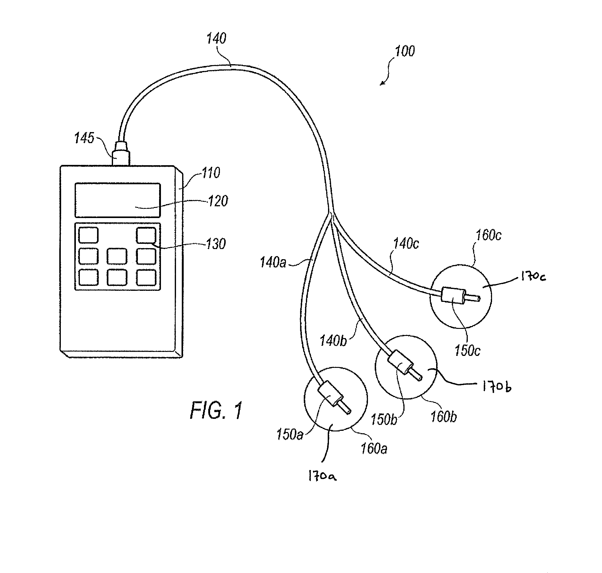
[0031]FIG. 1 illustrates an exemplary nerve monitoring device 100, including at least one mechanical sensor 160 in communication with a receiver 110 over a connector such as cable 140. In the illustrated approach, receiver 110 includes a display screen 120, and a user interface including a plurality of buttons 130. In one exemplary approach, a receiver, such as receiver 110, may include a touch screen which may provide information to a user and may also act as a user interface capable of receiving input from a user. Receiver 110 may also include one or more icons, light emitting diodes (LEDs), audible indicators, or other devices configured to provide information to a user. The illustrated cable 140 includes a primary connector 150 connected to receiver 110, and a plurality of secondary connectors 155 removably connected to a plurality of mechanical sensors 160.

[0032]The receiver 110 may be a stand alone receiver, as illustrated. It is to be understood, however, that this is by way ...


PUM


Abstract

A neural monitoring device includes a stimulator configured to provide a stimulus, a mechanical sensor configured to generate an output signal corresponding to a sensed event, and a receiver configured to receive an output signal from the mechanical sensor and determine if the output signal corresponds to the stimulus provided by the stimulator.

Description

CROSS REFERENCE TO RELATED APPLICATIONS[0001]This application is a continuation-in-part of and claims the benefit of priority from U.S. application Ser. No. 12 / 040,515, filed Feb. 29, 2008, which claims the benefit of priority to U.S. Provisional Application No. 60 / 980,996, filed Oct. 18, 2007, the entire disclosures of which are hereby incorporated by reference as though fully set forth herein. This application additionally claims the benefit of priority from U.S. Provisional Application Nos. 61 / 108,214, filed Oct. 24, 2008 and 61 / 229,530, filed Jul. 29, 2009, the entire disclosures of which are hereby incorporated by reference as though fully set forth herein.BACKGROUND INFORMATION[0002]Nerve injury is a major risk during surgical procedures. Traditional surgical practices emphasize the importance of recognizing or verifying the location of nerves to avoid injuring them. Advances in surgical techniques include development of techniques including ever smaller exposures, such as min...

Claims


Application Information

Patent Timeline
IPC IPC(8): A61B5/06A61B1/00A61B5/0488A61B5/00A61B5/11
CPCA61B5/0488A61B5/4893A61B5/1106A61B5/4029A61B2560/0412A61B2505/05A61B5/6828A61B5/7217A61B5/1107A61B5/1104A61B5/4519A61B5/6833A61B2562/0219A61B5/389
Inventor BARTOL, STEPHENWYBO, CHRISTOPHER
Owner INNOVATIVE SURGICAL SOLUTIONS
Learn More