Image forming apparatus and process cartridge
a technology of image forming apparatus and process cartridge, which is applied in the direction of electrographic process apparatus, instruments, optics, etc., can solve the problems of difficult to ensure a mounting locus, and achieve the effects of shortening the fpot, improving usability, and reducing the size of the image forming apparatus
- Summary
- Abstract
- Description
- Claims
- Application Information
AI Technical Summary
Benefits of technology
Problems solved by technology
Method used
Image
Examples
embodiment 1
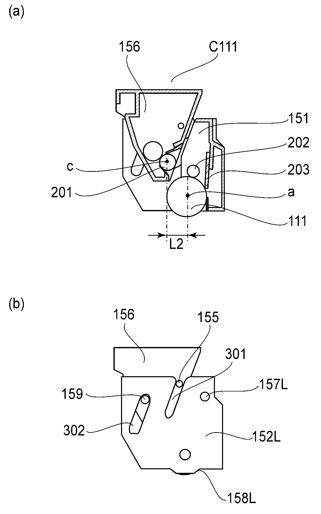
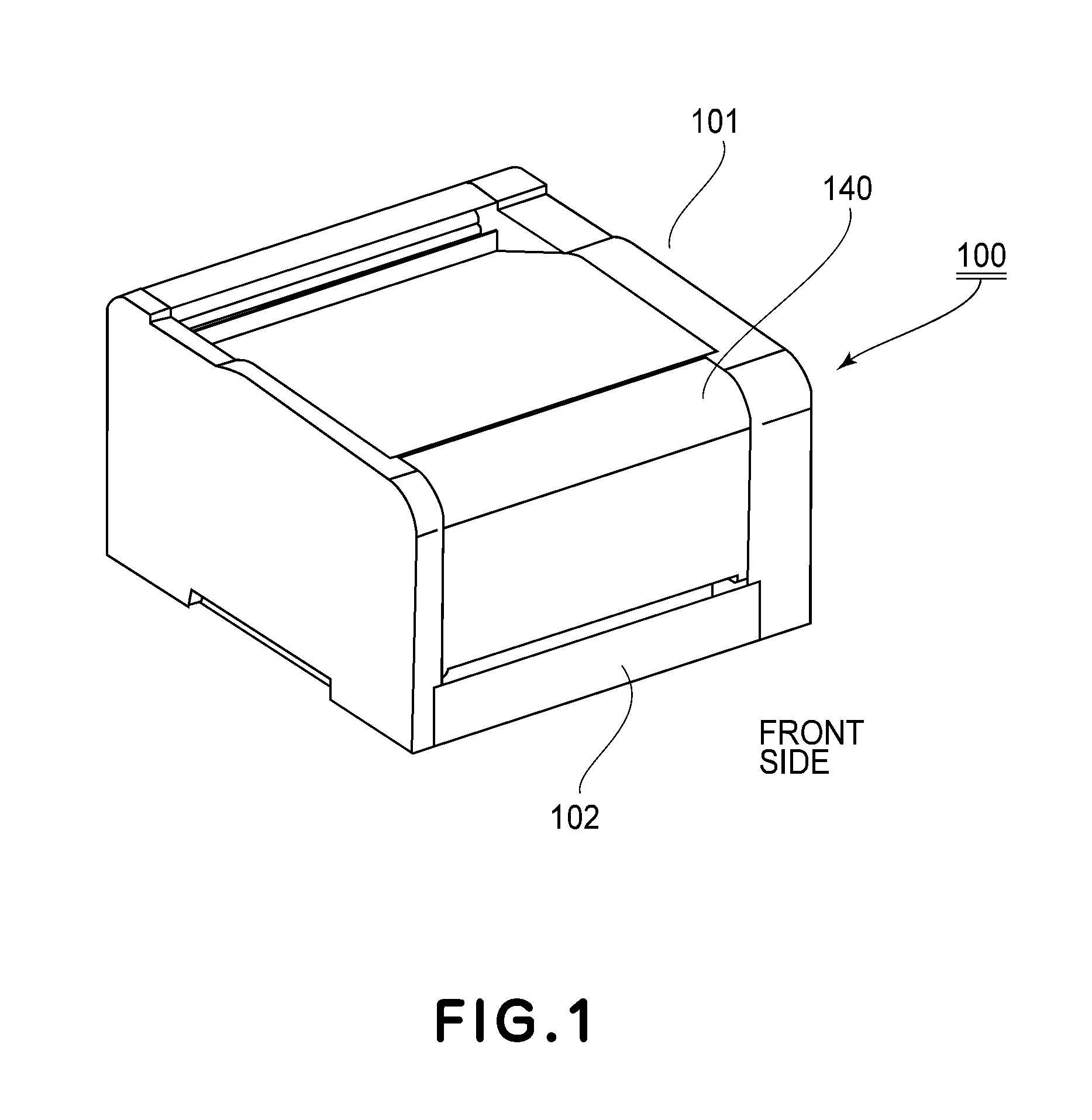
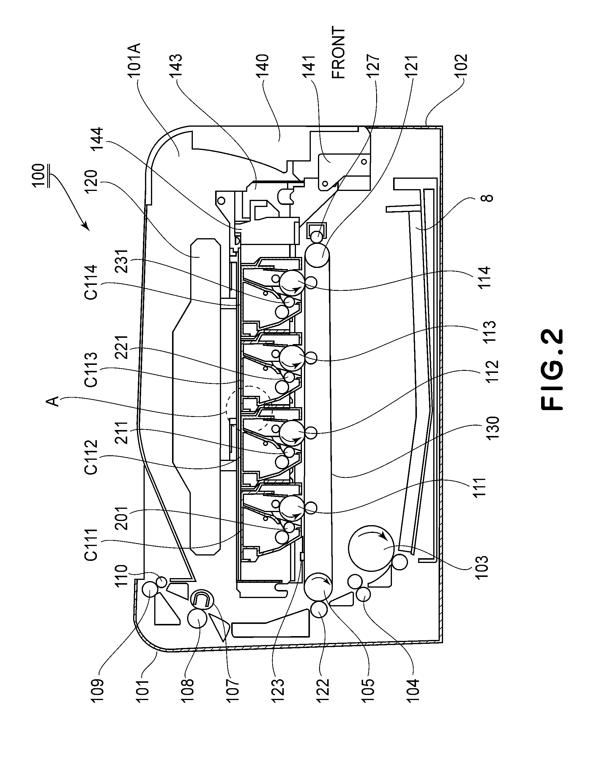
[0031]Embodiment 1 of the present invention will be described with reference to FIGS. 1-12. Description will be made in the order of a general structure of an image forming apparatus, a mounting and dismounting method of a process cartridge, a structure of the process cartridge and a slide movement constitution of a cartridge.
[0032]In this embodiment, as the image forming apparatus, an electrophotographic laser beam printer capable of forming a color image on a recording material is illustrated. Further, as the image forming apparatus, an image forming apparatus in which respective color toner images on photosensitive drums are successively transferred onto a belt (intermediary recording medium) and then are collectively transferred from the belt onto a recording material as a final recording medium is illustrated.
[0033]In this embodiment, a position where an image is formed on the photosensitive drum in contact with an intermediary transfer belt is defined as an “image forming posi...
embodiment 2
[0102]Embodiment 2 of the present invention will be described with reference to FIGS. 13-20. In this embodiment, constituent elements similar to the above-described constituent elements in Embodiment 1 will be omitted from description by adding the same reference numerals or symbols. In this embodiment, first to fourth process cartridges C211, C212, C213 and C214, and a cartridge tray 244 are used.
(Structure of Process Cartridge)
[0103]In this embodiment, the first to fourth process cartridges C211-C214 have the same contact developing method constitution.
[0104]That is, at the image forming position 100, the developing roller 201 in the developing unit 156 contacts the photosensitive drum 111 by using unshown flange member S. Further, other basic constitutions include the photosensitive member unit 151, the developing unit 156, the left side cover 152L and the right side cover 153R similarly as in Embodiment 1.
[0105]A general structure of each process cartridge C in this embodiment w...
embodiment 3
[0137]Embodiment 3 of the present invention will be described with reference to FIGS. 21 and 22. In this embodiment, constituent elements similar to the above-described constituent elements in Embodiments 1 and 2 will be omitted from description by adding the same reference numerals or symbols. In this embodiment, a cartridge tray 344 is used.
(Development Contact-and-Separation Constitution and Slide Movement Constitution of Cartridge)
[0138]With reference to FIGS. 21 and 22, the development contact-and-separation constitution and slide movement constitution as features of this embodiment will be described. FIG. 21 is a perspective view of an outer appearance of the cartridge tray 344. In FIG. 22, (a) to (c) are side views of outer appearances of the cartridge tray 344 with the pulling-out operation.
[0139]As shown in FIG. 22, each of the left and right tray holding members 143 is provided with a lift member 404 in the inside of the apparatus main assembly. As shown in (a) of FIG. 22,...
PUM
 Abstract
Description
Claims
Application Information
 - R&D
- Intellectual Property
- Life Sciences
- Materials
- Tech Scout
- Unparalleled Data Quality
- Higher Quality Content
- 60% Fewer Hallucinations
Browse by: Latest US Patents, China's latest patents, Technical Efficacy Thesaurus, Application Domain, Technology Topic, Popular Technical Reports.
© 2025 PatSnap. All rights reserved.Legal|Privacy policy|Modern Slavery Act Transparency Statement|Sitemap|About US| Contact US: help@patsnap.com


