Video signal coding apparatus and video signal coding method

a video signal and coding technology, applied in signal generators with optical-mechanical scanning, color televisions with bandwidth reduction, etc., can solve the problems of inability to transmit the data of captured images in real time, failure to prevent overflow of code amounts, etc., to achieve the effect of avoiding imposing large loads on processing time and performance for coding and on required memory spa

Active Publication Date: 2015-06-23
PANASONIC SEMICON SOLUTIONS CO LTD
View PDF16 Cites 2 Cited by
  • Summary
  • Abstract
  • Description
  • Claims
  • Application Information

AI Technical Summary

Benefits of technology

[0047]According to the present invention, even when overflow of a code amount occurs, a bit stream adapted to a predetermined rate control can be generated without imposing large loads on processing time and performance for coding and on required memory space.

Problems solved by technology

Moreover, in the case of directly transmitting data of captured images by way of a transmission path through which data of limited size can be transmitted, it is not possible to transmit the data of captured images in real time.
However, even with such per-picture control on a quantization parameter as to avoid overflow and underflow of a video buffer, there is a problem of a failure to prevent overflow of the code amount, for example, for an image which includes fine patterns or a scene with drastic motion such as a scene change.

Method used


Image

  • Video signal coding apparatus and video signal coding method
  • Video signal coding apparatus and video signal coding method
  • Video signal coding apparatus and video signal coding method

Examples


Embodiment Construction

[0062]The following shall describe an embodiment for implementing the present invention with reference to the drawings.

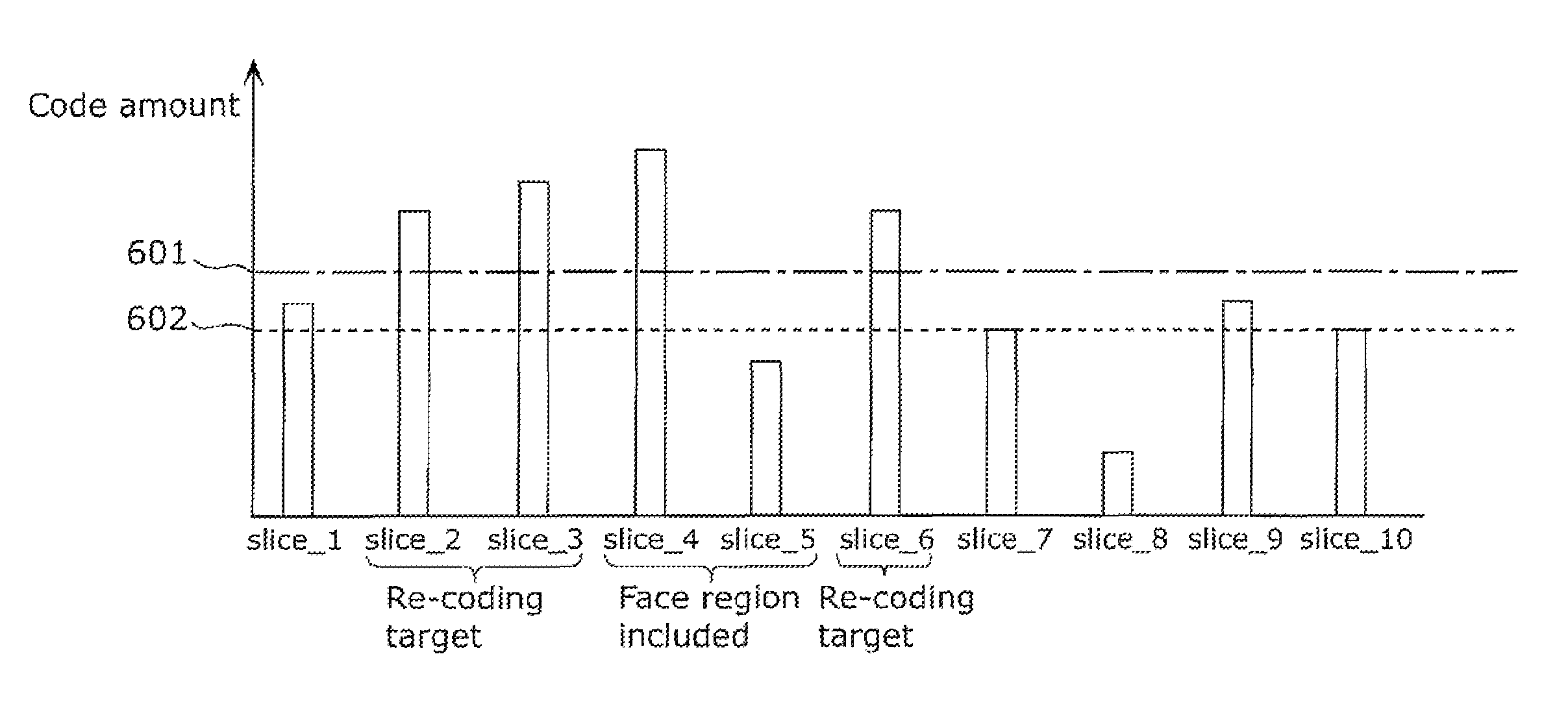
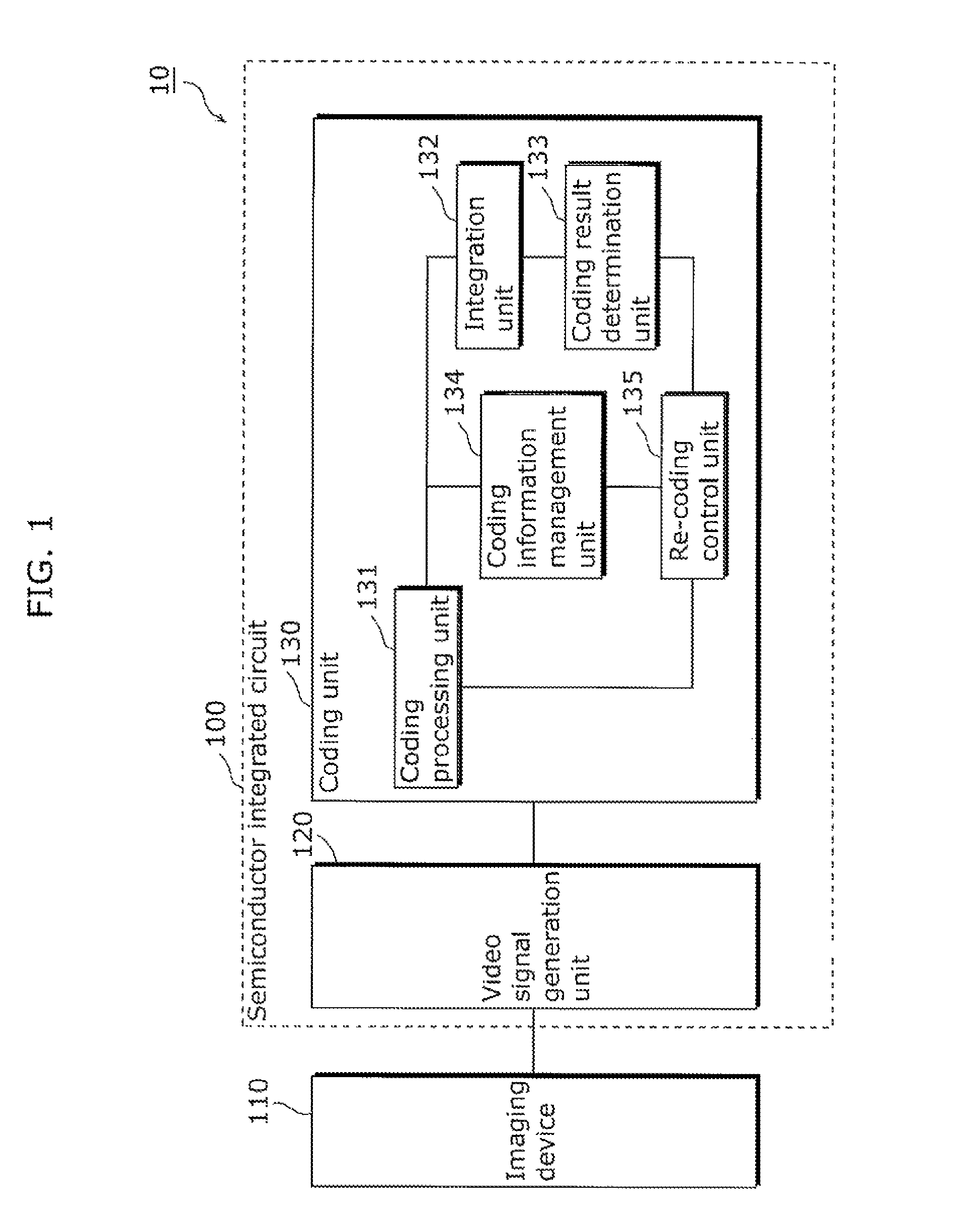
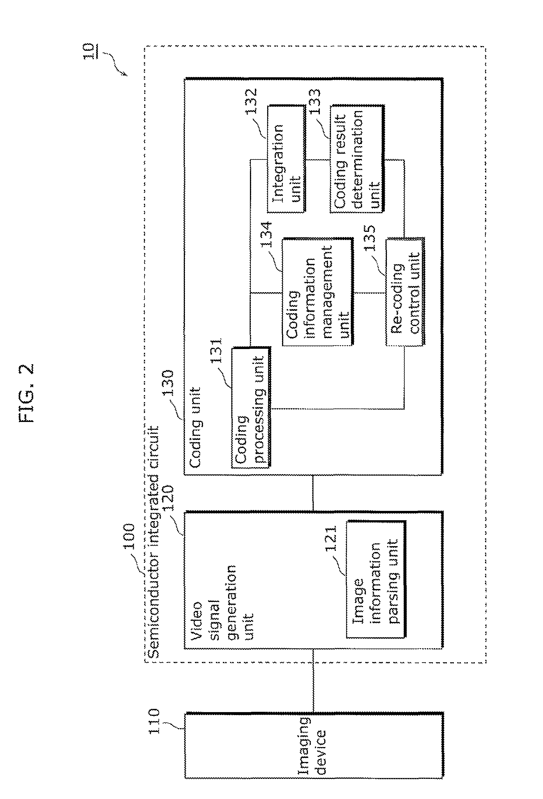
[0063]A video signal coding apparatus according to an embodiment of the present invention includes: a coding processing unit configured to code a current picture to generate coded data; a coding result determination unit configured to determine whether or not a code amount of the coded data is greater than a predetermined threshold, and determine that re-coding processing on the current picture is necessary when determining that the code amount is greater than the threshold; and a re-coding control unit configured to specify a re-coding target slice based on coding information indicating a feature of the coded data when the coding result determination unit determines that the re-coding processing is necessary, and the coding processing unit is configured to perform the re-coding processing on the slice specified by the re-coding control unit.

[0064]First, a structure...


PUM


Abstract

A video signal coding apparatus includes a coding unit which codes and re-codes a video signal and includes: a coding processing unit which codes, slice-by-slice, a current picture indicated by the video signal, to generate coded data; an integration unit which calculates a code-integrated value indicating a code amount of the coded data; a coding result determination unit which determines that re-coding of the current picture is necessary when determining that the code-integrated value is grater than a threshold; and a re-coding control unit which specifies a slice to be re-coded, based on coding information indicating a feature of the coded data, when it is determined that the re-coding is necessary, and the coding processing unit further re-codes the slice specified by the re-coding control unit.

Description

CROSS REFERENCE TO RELATED APPLICATIONS[0001]This is a continuation application of PCT Patent Application No. PCT / JP2011 / 000396 filed on Jan. 26, 2011, designating the United States of America, which is based on and claims priority of Japanese Patent Application No. 2010-025742 filed on Feb. 8, 2010. The entire disclosures of the above-identified applications, including the specifications, drawings and claims are incorporated herein by reference in their entirety.TECHNICAL FIELD[0002]The present invention relates to video signal coding apparatuses and methods for coding and transmitting or recording video signals and particularly relates to video signal coding apparatus and method in which video signals are re-coded to generate coded image data which satisfies a target bit rate.BACKGROUND ART[0003]Recent years have seen a wide spread of moving image capturing devices, still image capturing devices, and moving and still image capturing devices, such as digital video cameras, digital ...

Claims


Application Information

Patent Timeline
Patent Type & Authority Patents(United States)
IPC IPC(8): H04N19/194H04N19/115H04N19/15H04N19/174H04N19/00H04N19/12H04N19/124H04N19/139H04N19/146H04N19/156H04N19/186H04N19/189H04N19/196H04N19/423H04N19/503H04N19/51
CPCH04N19/194H04N19/15H04N19/115H04N19/174
Inventor SHIMIZU, MINAKOIWAHASHI, KENJI
Owner PANASONIC SEMICON SOLUTIONS CO LTD
Why Eureka
Try Eureka