
Planar Vivaldi antenna array

a vivaldi antenna and array technology, applied in the field of antennas, can solve the problems of difficult operation, difficult accessing with a soldering iron or other equipment along the full depth of the board e.g. 50 mm,

Active Publication Date: 2015-06-09
BAE SYSTEMS PLC
View PDF15 Cites 31 Cited by
  • Summary
  • Abstract
  • Description
  • Claims
  • Application Information

AI Technical Summary

Benefits of technology

This patent describes a new type of antenna array that can be easily fixed together using grooves and slots. The cross-sectional shape of the grooves and slots are complementary, which allows for easier sliding of the antenna arrays together. The surfaces of the arrays can be electrically conductive, and conductive epoxy can be used to bond them together. This design makes it easier to create complex antenna structures and ensures optimal performance.

Problems solved by technology

This is difficult to perform, and this difficulty is exacerbated by the consideration that good electrical contact is required in all of these areas for the antenna array to perform well.
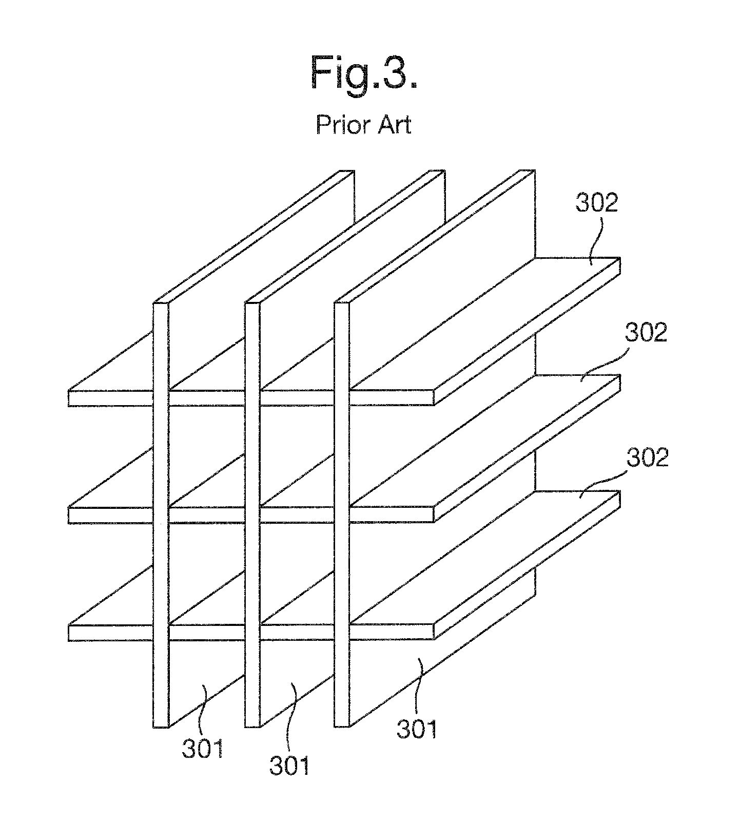
Furthermore, the physical sizes involved are small, e.g. the width of the antenna element may be e.g. 5 mm, in which case the resulting square cell size is e.g. 5 mm×5 mm, which therefore makes accessing with a soldering iron or other equipment along the full depth of the board e.g. 50 mm difficult.

Method used


Image

  • Planar Vivaldi antenna array
  • Planar Vivaldi antenna array
  • Planar Vivaldi antenna array

Examples


Embodiment Construction

[0025]In the following description, terminology such as “vertical”, “horizontal” etc. is adopted to describe elements of the invention. It will be appreciated by the skilled person that such terminology is not limiting and is used merely to refer to the position of one element relative to other elements.

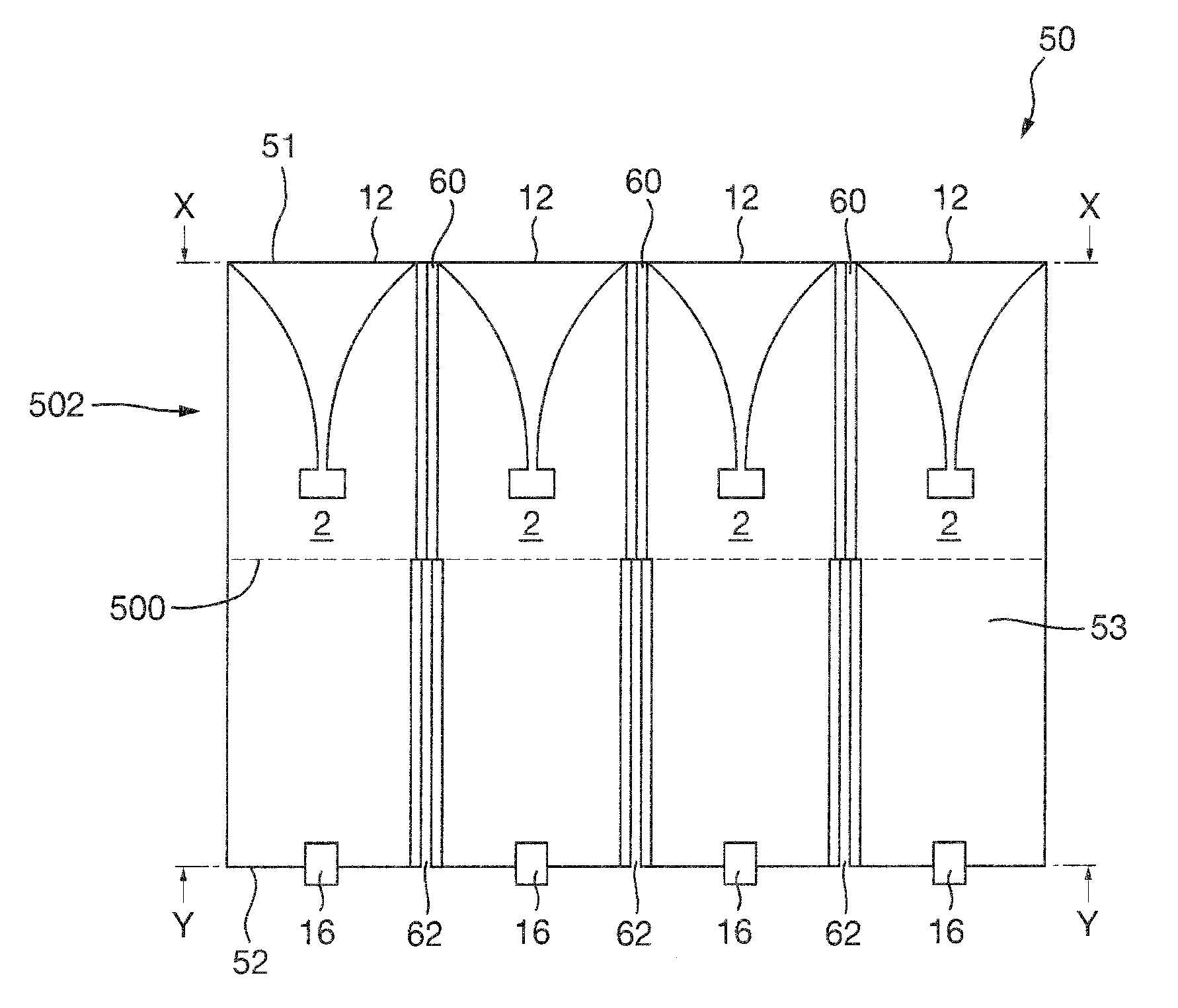
[0026]FIG. 4 is a schematic illustration of a Vivaldi antenna array 50 according to a first embodiment of the present invention. In particular, FIG. 4 shows features of a top surface 53 of the Vivaldi antenna array 50. Features of further surfaces of the Vivaldi antenna array 50 are described in more detail later below with reference to FIGS. 5 and 6. In this embodiment, the Vivaldi antenna array 50 comprises four Vivaldi antenna elements 2 arranged in a row 502. In the row 502, the four Vivaldi antenna elements 2 are positioned side-by-side such that the open ends 12 of the Vivaldi antenna elements 2 are level and form a first edge 51 of the Vivaldi antenna array 50, along the direc...


PUM

PropertyMeasurementUnit
sizeaaaaaaaaaa
sizeaaaaaaaaaa
widthaaaaaaaaaa

Abstract

A planar Vivaldi antenna array, and method of forming such an array, the array comprising: a plurality of slots at an end of the antenna array, the slots extending through the whole thickness of the planar structure of the antenna array; and a plurality of grooves extending from the slots; wherein: the grooves do not extend through the whole thickness of the planar structure of the antenna array; and the cross-sectional shape of the grooves is complementary to the cross-sectional shape of the slots.

Description

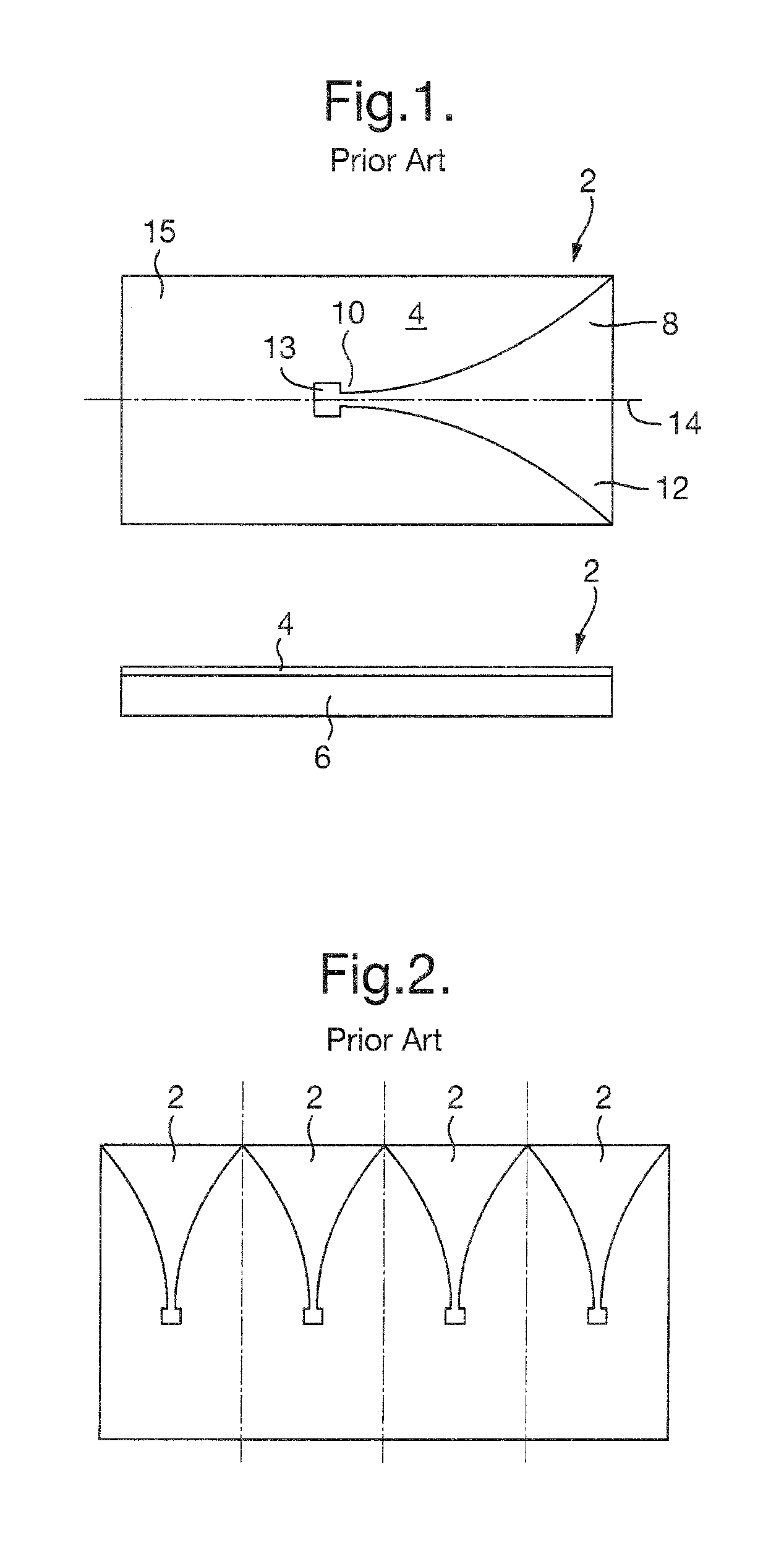
FIELD OF THE INVENTION[0001]The present invention relates to antennas. In particular, the present invention relates to, but is not limited to, arrays of Vivaldi antenna elements, for example dual-polarised Vivaldi antenna arrays.BACKGROUND[0002]Tapered-slot, or Vivaldi, antenna elements are known. A Vivaldi antenna element is a co-planar broadband-antenna. The Vivaldi antenna element 2 comprises a conductive layer 4 disposed on a substrate 6. The conductive layer 4 is disposed on the substrate 6 such that a space 8 in the conductive layer 4 is formed. The distance between the sides of the space 8 widens from a minimum at a narrow end 10 of the space 8 to a maximum at an open end 12 of the space 8. At the narrow end 10, a square, or circular, or other shaped region 13 without conductor is provided. In conventional Vivaldi antenna elements, the space 8 is symmetrical about a central axis 14. Further conductor material 15 extends beyond the narrow end 10 and the region 13.[0003]It is k...

Claims


Application Information

Patent Timeline
Patent Type & Authority Patents(United States)
IPC IPC(8): H01Q13/10H01Q13/08H01Q21/00H01Q21/06H01Q21/24F16B5/06
CPCH01Q13/10F16B5/0614H01Q13/085H01Q21/0087H01Q21/064H01Q21/24Y10T29/49016
Inventor GUY, RONALD FRANK EDWARDTWEEN, LARRY BRIANPANAGHISTON, GARY DAVIDPIROLLO, BRUNO PETER
Owner BAE SYSTEMS PLC
Learn More