
Scene scan

a technology for scanning scenes and images, applied in the field of organizing photographic images, can solve problems such as the inability of programs to stitch photographic images together, and the inability to align images perfectly

Active Publication Date: 2015-06-02
GOOGLE LLC
View PDF14 Cites 19 Cited by
  • Summary
  • Abstract
  • Description
  • Claims
  • Application Information

AI Technical Summary

Benefits of technology

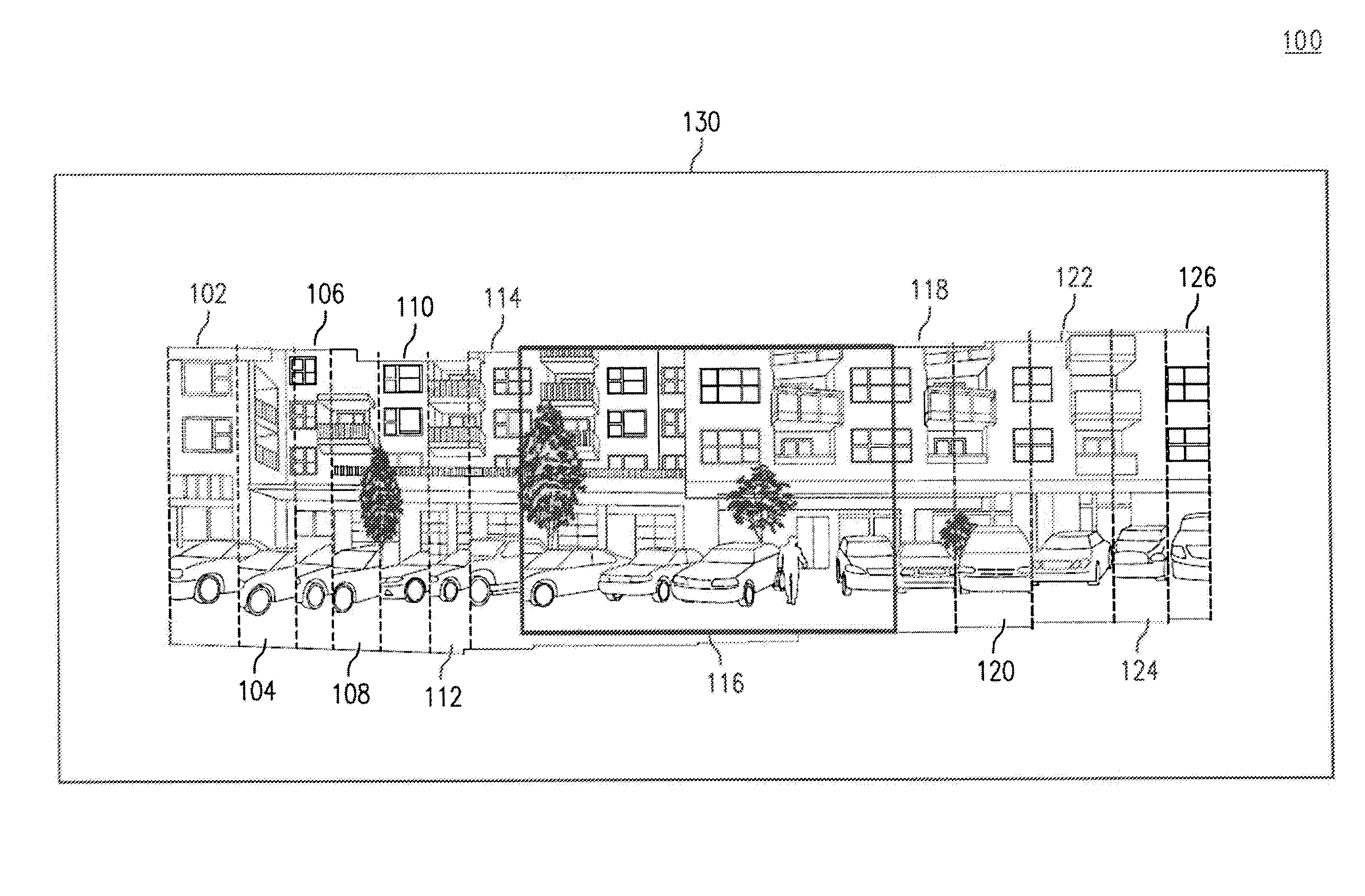
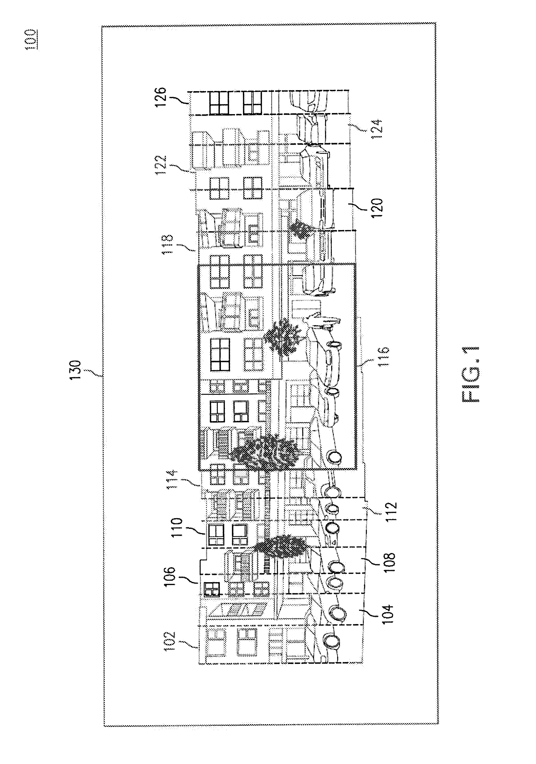
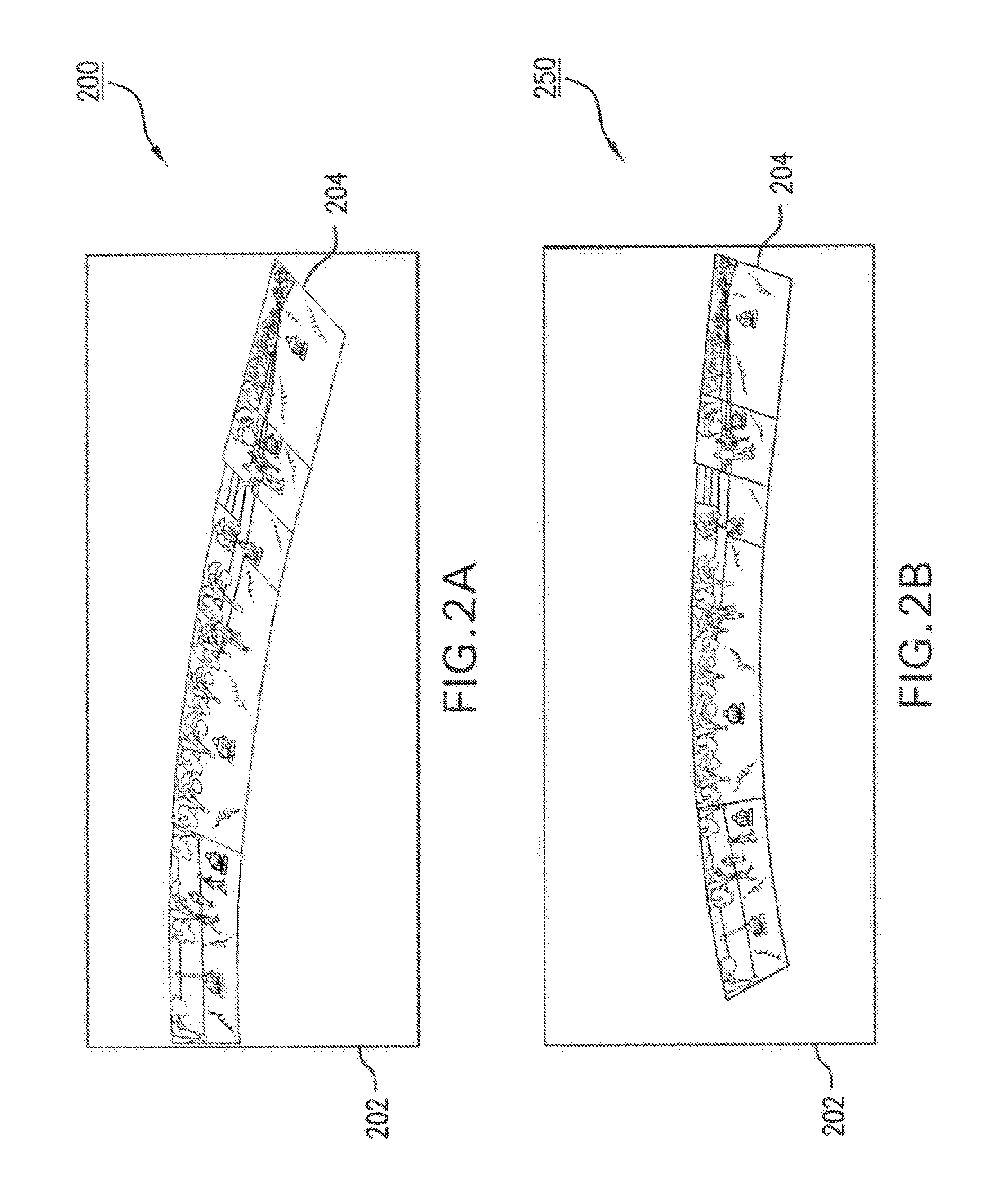
The embodiments described herein describe a system and method for creating a scene scan from a group of photographic images. This involves detecting common features in the images and then aligning them using a similarity transform that includes a rotation factor, scaling factor, and translation factor. The result is a more accurate and detailed scan of the scene captured in the images.

Problems solved by technology

These computer programs, however, are not designed to stitch photographic images together when the photographic images are captured from different optical centers.
If the image capture device does not rotate about its optical center, its images may become impossible to align perfectly.

Method used


Image

  • Scene scan
  • Scene scan
  • Scene scan

Examples


example system embodiments

[0031]FIG. 4A illustrates an example system 400 for creating a scene scan from a group of photographic images according to an embodiment. System 400 includes computing device 402. Computing device 402 includes feature detector module 406, similarity transform module 408, data output module 410, rendering module 412, user-interface module 414, counter-rotation module 416, and camera 418.

[0032]FIG. 4B illustrates an example system 450 for creating a scene scan from a group of photographic images according to an embodiment. System 450 is similar to system 400 except that some functions are carried out by a server. System 450 includes computing device 452, image processing server 454, scene scan database 456 and network 430. Computing device 452 includes rendering module 412, user-interface module 414, and camera 418. Image processing server 454 includes feature detector module 406, similarity transform module 408, data output module 410, and counter-rotation module 416.

[0033]Computing ...

example method embodiments

[0064]FIG. 5 is a flowchart illustrating a method 500 that may be used to create a scene scan from a group of photographic images according to an embodiment. While method 500 is described with respect to an embodiment, method 500 is not meant to be limiting and may be used in other applications. Additionally, method 500 may be carried out by, for example, system 400 in FIG. 4A or system 450 in FIG. 4B.

[0065]Method 500 first determines a set of common features for at least one pair of photographic images included in the group of photographic images (stage 510). The set of common features includes at least a portion of an object captured in each of a first and a second photographic image included in the at least one pair, where the first and second photographic images may be captured from different optical centers. Any feature detection method may be used to determine the set of common features for the photographic images included in a pair. Such methods may include, for example, Feat...


PUM


Abstract

Systems, methods, and computer storage mediums are provided for creating a scene scan from a group of photographic images. An exemplary method includes determining a set of common features for at least one pair of photographic images. The features include a portion of an object captured in each of a first and a second photographic image included in the pair. The first and second photographic images may be captured from different optical centers. A similarity transform for the at least one pair of photographic images is the determined. The similarity transform is provided in order to render the scene scan from each pair of photographic images. At least one of the rotation factor, the scaling factor, or the translation factor associated with the similarity transform is used to position each pair of photographic images such that the set of common features between a pair of, at least in part, align.

Description

[0001]This application claims the benefit of U.S. Provisional Application No. 61 / 577,931 filed Dec. 20, 2011, which is incorporated herein in its entirety by reference.FIELD[0002]The embodiments described herein generally relate to organizing photographic images.BACKGROUND[0003]Users wishing to stitch together a collection of photographic images captured from the same optical center may utilize a variety of computer programs that determine a set of common features in the photographic images and stitch the photographic images together into a single panorama. The photographic images may be aligned by matching the common features between the photographic images. These computer programs, however, are not designed to stitch photographic images together when the photographic images are captured from different optical centers. Panorama creation programs known in the art require that an image capture device rotate about the optical center of its lens, thereby maintaining the same point of p...

Claims


Application Information

Patent Timeline
Patent Type & Authority Patents(United States)
IPC IPC(8): G06T11/00G06T3/40
CPCG06T11/00G06T3/4038
Inventor SEITZ, STEVEN MAXWELLGARG, RAHUL
Owner GOOGLE LLC
Learn More