
System and method for remote full field three-dimensional displacement and strain measurements

a full field, three-dimensional displacement and strain technology, applied in the field of systems for measuring and visualizing the full field of deformation behavior of bodies, can solve problems such as difficulty in applying uniform grids, and achieve the effect of out-of-range compactness ratio

Active Publication Date: 2015-06-02
UNITED STATES OF AMERICA +1
View PDF16 Cites 6 Cited by
  • Summary
  • Abstract
  • Description
  • Claims
  • Application Information

AI Technical Summary

Benefits of technology

The patent text describes a method for identifying characteristic points of dots in images. The method involves integrating the images to find the centroid of each dot. The method also includes eliminating irregular objects from both images by identifying objects with low dot intensity, unnatural pixel area, or out-of-range characteristics. The technical effect of this patent is to provide a reliable and accurate method for identifying characteristic points of dots in images.

Problems solved by technology

It can be difficult to apply a uniform grid to irregularly shaped bodies, and any inaccuracies in the application of the grid are a major source of errors in the measurement of deformation.

Method used


Image

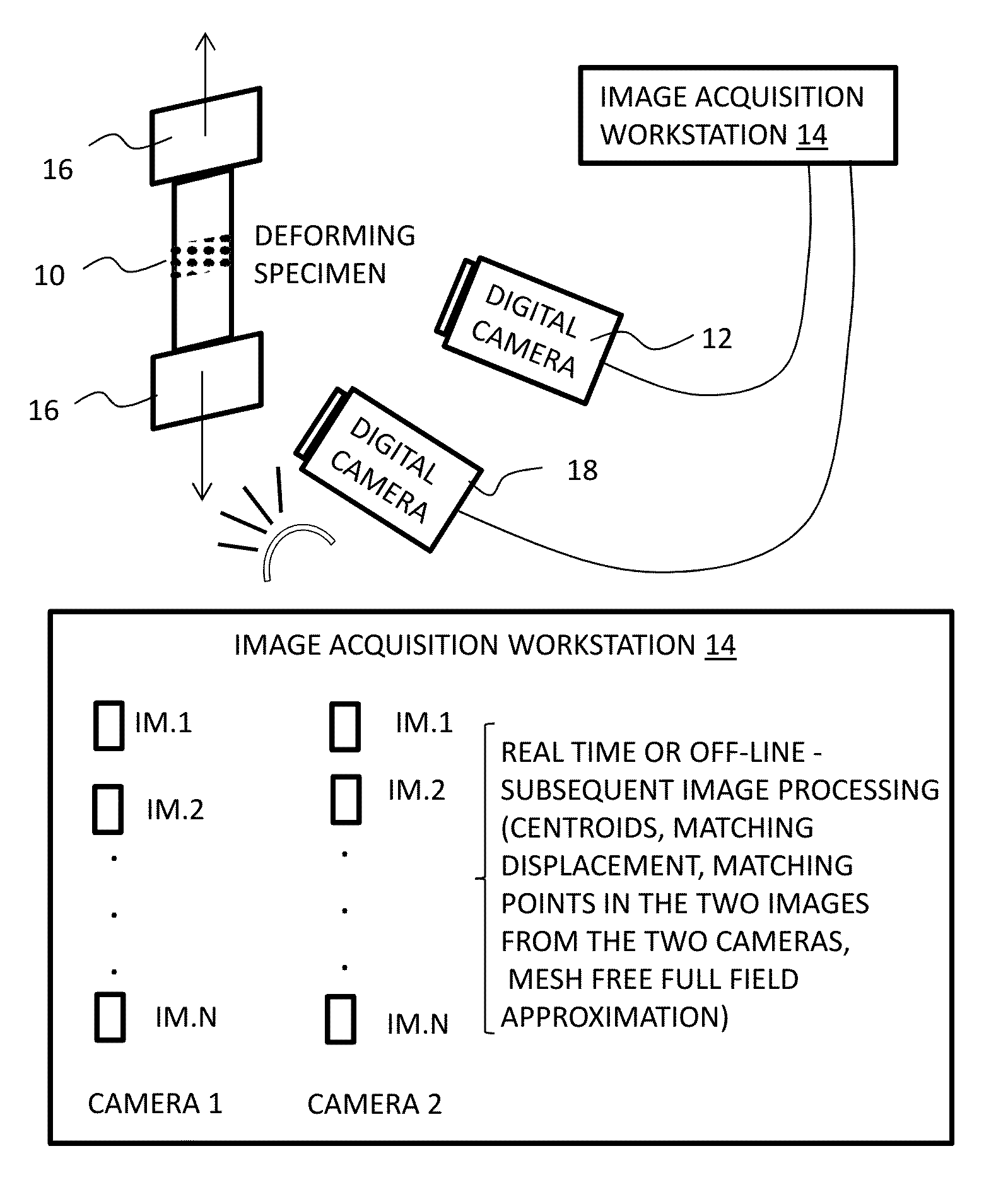
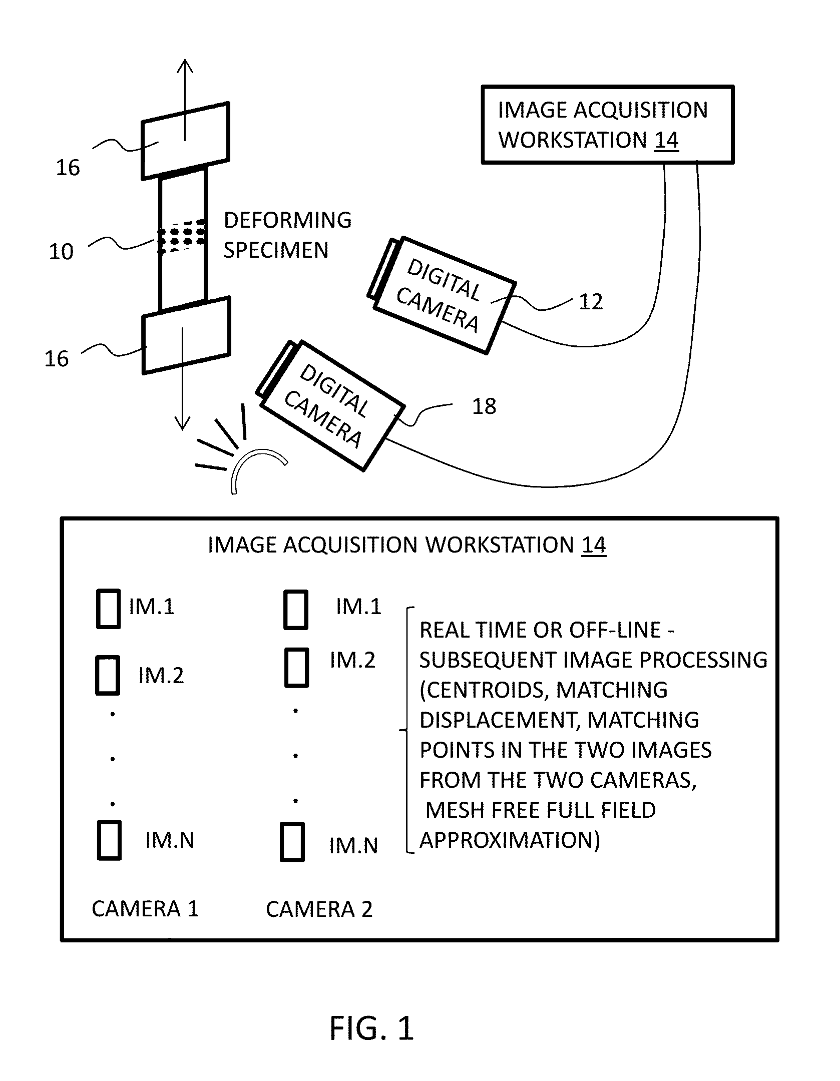
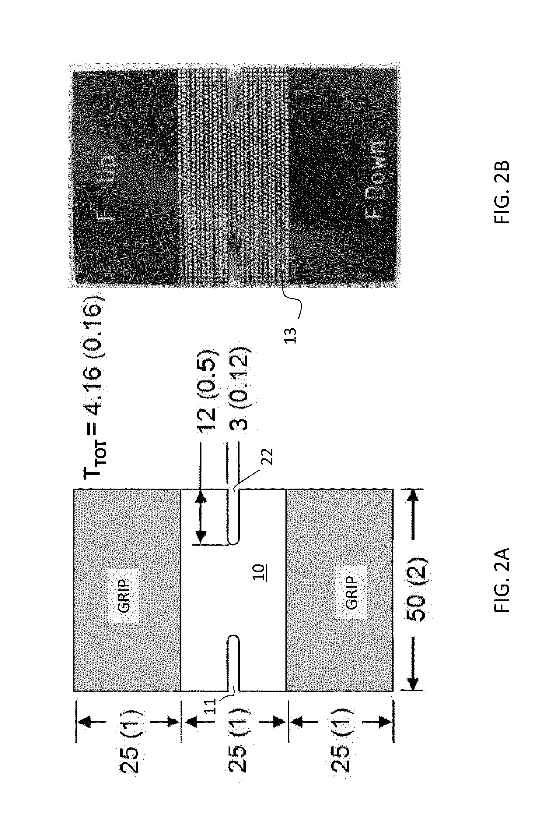
  • System and method for remote full field three-dimensional displacement and strain measurements
  • System and method for remote full field three-dimensional displacement and strain measurements
  • System and method for remote full field three-dimensional displacement and strain measurements

Examples


Embodiment Construction

[0038]The following description discloses a computational workbench infrastructure that implements a Meshless Random Grid (MRG) method for the remote (non-contact) measurement of displacement and strain fields in three dimensional space. The method is applicable to structures bounded by flat surfaces that deform under various mechanical and generalized loading conditions in and out of plane.

[0039]The workbench can provide efficient and inexpensive displacement and strain field determination as a critical element of a data-driven material characterization methodology via mechatronically automated robotic testing machines, using a mesh-free (or mesh-less), random grid (MRG) method that takes advantage of the properties of mesh-free approximations to represent the displacement and strain fields. These properties include the ability to represent high order continuity of the underlying field, the ability to handle irregular domains and nodal distributions of general nature (deterministic...


PUM

PropertyMeasurementUnit
Displacementsaaaaaaaaaa
thicknessaaaaaaaaaa
tensionaaaaaaaaaa

Abstract

A method and system for measuring full field deformation characteristics in three dimensions of a body upon which a pattern of visible marks has been applied. The method includes receiving images of the pattern of marks from at least two digital video cameras as the specimen deforms. A computer processor identifies the centroids of each of the two camera images of the body in a first frame, matches the centroids of the marks in the two images, and generates a three-dimensional representation of the centroids based on the two images, and repeats these steps for the images from the two cameras in a subsequent frame. The computer processor calculates the displacement vector between a three dimensional representation of the centroids and the subsequent three dimensional representation of the centroids, and calculates full field displacement and strain fields based on the displacement vector.

Description

CROSS-REFERENCE TO RELATED APPLICATIONS[0001]This Application is a non-provisional under 35 USC 119(e) of, and claims the benefit of U.S. Provisional Application 61 / 514,083 filed on Aug. 2, 2011, and claims the benefit of U.S. Provisional Application 61 / 514,092 filed on Aug. 2, 2011, the entire disclosure of both documents being incorporated herein in their entireties.BACKGROUND[0002]1. Technical Field[0003]The present invention relates generally to a system for measuring and visualizing the full field of deformation behavior of a body in terms of displacement and strain, and more specifically, to a methodology, algorithms and a corresponding set of tools for the data acquisition, digital image processing, field variable approximation or interpolation and visualization of digital images of a deforming body in three dimensions.[0004]2. Background Technology[0005]Beginning in the 1980's, digital imaging has been used to measure the deformation state of deformable material specimens. T...

Claims


Application Information

Patent Timeline
Patent Type & Authority Patents(United States)
IPC IPC(8): H04N13/02G01B11/16G01N3/06G06T7/00
CPCG01B11/165G06T7/0075G01N3/068G01N2203/0017G01N2203/0218G01N2203/0647G06T7/593
Inventor MICHOPOULOS, JOHN G.ILIOPOULOS, ATHANASIOSANDRIANOPOULOS, NIKOS P.
Owner UNITED STATES OF AMERICA
Learn More