
Double tool pouch with retractor pockets

a tool pouch and retractor technology, applied in the field of tool accessories, can solve the problems of skupin's approach to a tool pouch having a plurality of tool pockets, poor positioning of the retractor compartment on the back side of the tool bag for a tool stored in nested tool pockets, and the web of tethers, so as to achieve the effect of quick switch

Inactive Publication Date: 2015-05-26
PURE SAFETY GRP INC
View PDF16 Cites 8 Cited by
  • Summary
  • Abstract
  • Description
  • Claims
  • Application Information

AI Technical Summary

Benefits of technology

The present invention aims to improve the efficiency and safety of workers by allowing them to easily switch between tethered tools without interference from other tools' tethers. This is achieved by designing a tool bag with nested pouches and retractable tethers that originate from the rear of the tool holder. This design prevents tangling and cross-reach of multiple lines of tethers, which could otherwise be time-consuming and tedious for workers to scrutinize. By providing this solution, workers can quickly and easily switch tools without being hindered by tethered tools.

Problems solved by technology

However, the approach taken by Skupin is not optimal for a tool pouch having a plurality of tool pockets, where one or more pocket is nested or located at least partially within another pocket.
A retractor compartment located on the back side of the tool bag is poorly positioned for a tool stored in nested tool pockets.
A tool bag with two or more nested pouches and having tethers that all originate from retractors located in the rear part of the tool holder would result in a web of tethers that prevent access to some tools and that easily become tangled unless the user is diligent about observing removal and replacement of a tool from the pouch so as to prevent crossing or tangling multiple lines.

Method used


Image

  • Double tool pouch with retractor pockets
  • Double tool pouch with retractor pockets
  • Double tool pouch with retractor pockets

Examples


Embodiment Construction

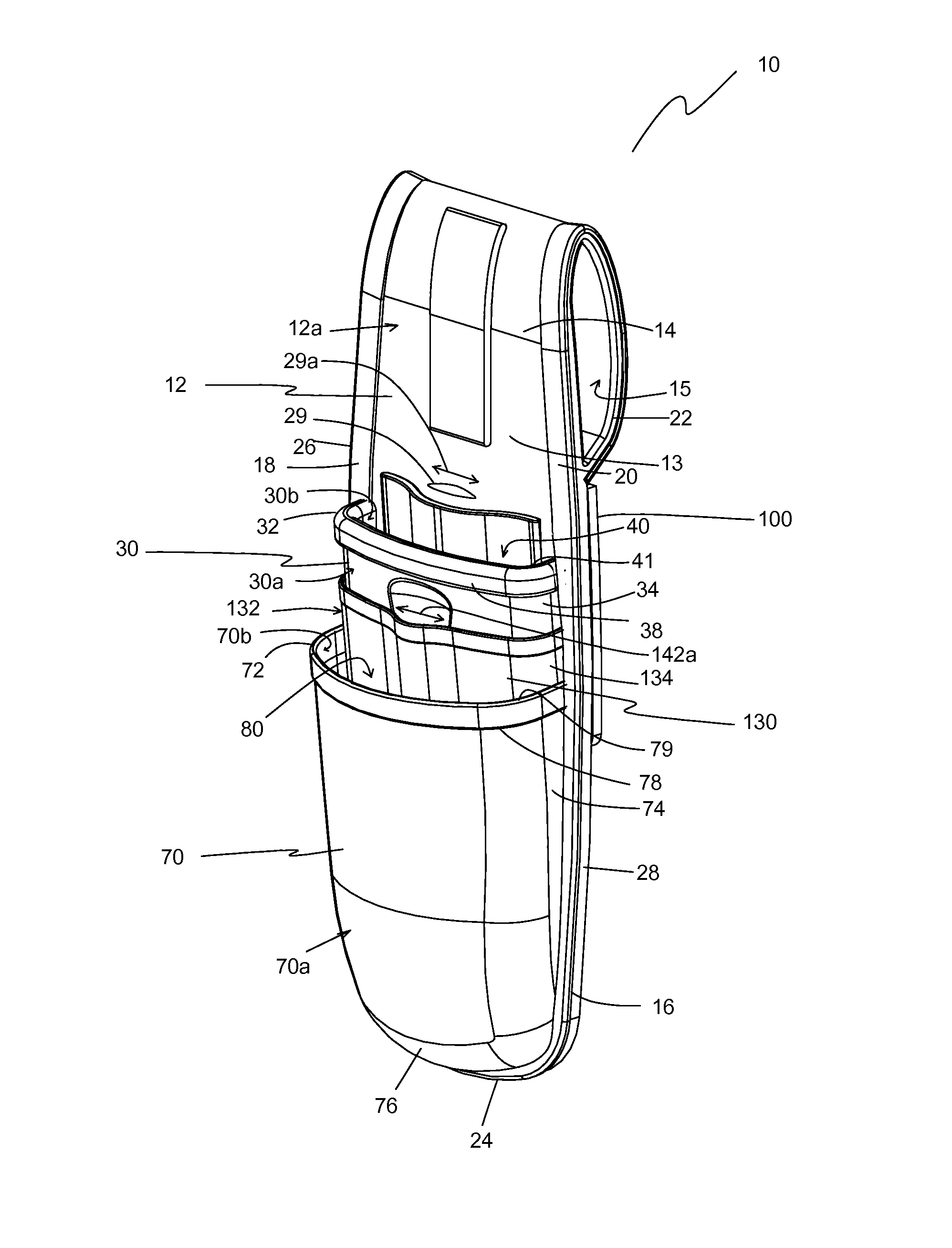
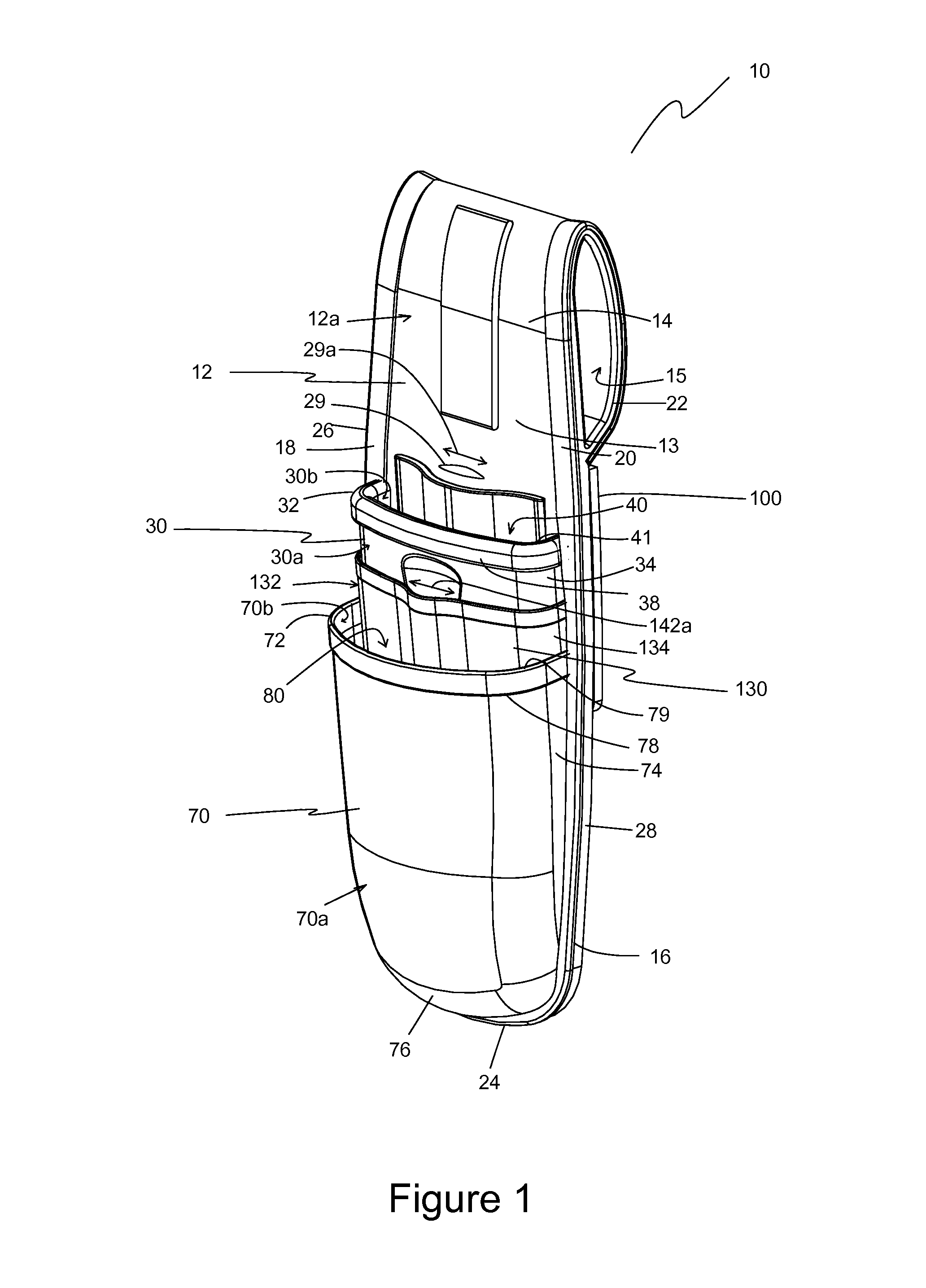
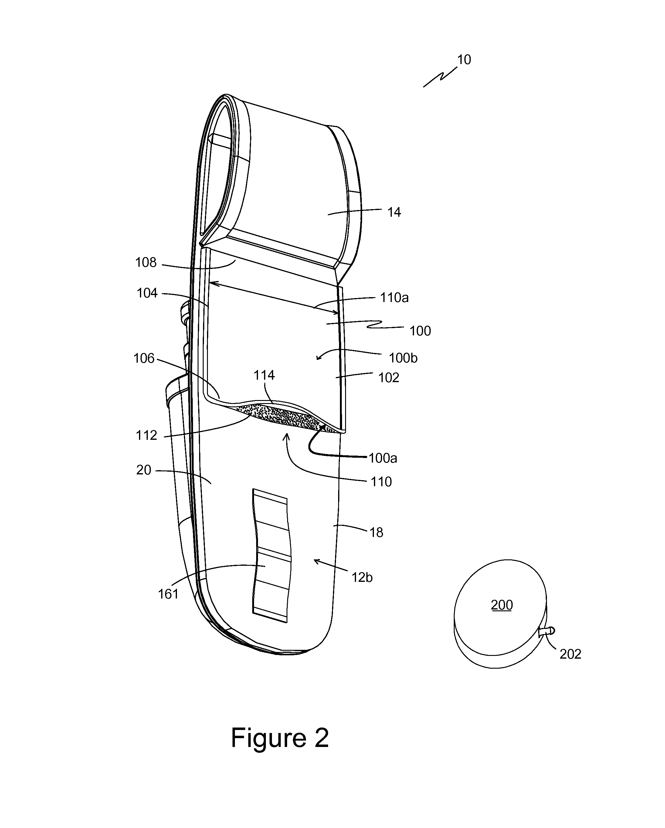
[0031]The preferred embodiments of the present invention are illustrated in FIGS. 1-6. FIG. 1 illustrates one embodiment of a tool holder 10 that includes a substrate 12, a first tool pouch 30, a first retractor pocket 100, a second tool pouch 70, and a second retractor pocket 130. In one embodiment, substrate 12 has a vertically-elongated body portion 13, an upper end 14 portion, a lower end portion 16, a first side portion 18, a second side portion 20, a front surface 12a, and a back surface 12b (shown in FIG. 2). It is intended that front surface 12a faces away from the user's body and back surface 12b faces towards and / or rests against the user's body when tool holder 10 is worn on a tool belt. Substrate 12 defines a first retractor opening 29 with a first retractor opening width 29a. First retractor opening 29 is preferably a slit or narrow opening; other shapes, such as round, rectangular, or oval are also acceptable. First retractor opening 29 extends through substrate 12 and...


PUM


Abstract

A tool holder has a first tool pouch connected to the front surface of a substrate and defining a first tool compartment between the first tool pouch and the substrate. A second tool pouch is connected to the front surface of the substrate and defines a second tool compartment between the second tool pouch and the substrate, where the first tool pouch is at least partially disposed within the second tool pouch. A first retractor pocket is attached to the back surface of the substrate and defines a first retractor compartment that communicates through an opening in the substrate to the first tool compartment. A second retractor pocket attached to the first tool pouch front surface and defines a second retractor compartment between the second retractor pocket and the first tool pouch. The second retractor compartment communicates through a second retractor opening to the second tool compartment.

Description

[0001]This application claims the benefit of U.S. provisional application Ser. No. 61 / 856,497, filed on Jul. 19, 2013.BACKGROUND OF THE INVENTION[0002]1. Field of the Invention[0003]The present invention relates generally to tool accessories and more particularly to a tool pouch with retractor pockets.[0004]2. Description of the Prior Art[0005]Carpenters, electricians, facilities maintenance personnel, and other workers often use a tool belt or pouch to hold tools. One example is a tool pouch that attaches to a tool belt and is designed to hold a small number of tools, such as a pouch to hold a pair of pliers and one or two screwdrivers. Tool pouches of this type are useful for storing tools between tasks and help to prevent misplaced tools.[0006]In addition to preventing misplaced tools, workers seek to avoid accidental drops, particularly when working on a ladder, scaffold, or other elevated location. Lanyards, tethers, hooks, and similar restraints have been used to prevent accid...

Claims


Application Information

Patent Timeline
Patent Type & Authority Patents(United States)
IPC IPC(8): B65H75/40A45F5/02A45F5/00A45F5/10
CPCA45F5/02A45F5/004A45F5/022A45F2200/05A45F2005/108A45F5/102A45F5/021A45F2200/0575
Inventor MOREAU, DARRELL A.MOREAU, ANDRE W.
Owner PURE SAFETY GRP INC
Learn More