Lock mechanism and related electronic device

a technology of electronic devices and latch mechanisms, applied in the direction of casings/cabinets/drawers, casings/cabinets/drawers, instruments, etc., can solve the problems of reducing the quality impression and satisfaction of notebook computers with the conventional latch mechanism, and achieves the effect of low manufacturing cost, simple structure and low volume of the lock mechanism

Active Publication Date: 2015-05-19
WISTRON CORP
View PDF5 Cites 7 Cited by
  • Summary
  • Abstract
  • Description
  • Claims
  • Application Information

AI Technical Summary

Benefits of technology

[0017]The lock mechanism of the present invention connects the first actuating portion and the second actuating portion of the actuating component respectively to the constraining component and the recovering component. When the actuating component is pressed, the first actuating portion can utilize the bridging component to move the constraining component, so as to separate the wedged structure from the fix portion. Meanwhile, the second actuating portion slides relative to the second inclined structure, so the first inclined structure of the recovering component can push the fix portion to separate the electronic component from the sunken structure. As the external force applied to the actuating component is removed, the resilient recovering force of the resilient component reversely drives the recovering component, and the recovering component can push the actuating component out of the hole on the base. Due to the movement of the actuating component, the first actuating portion can push the constraining component via the bridging component, and the lock mechanism is back to the initial mode. It is to say, the lock mechanism of the present invention can be utilized to release the constraint of the fix portion by the constraining component and to drive the recovering component to push the fix portion for separation of the electronic component simultaneously by one touch. Therefore, the lock mechanism of the present invention has advantages of simple structure, operation convenience and low manufacturing cost. The present invention can guide the perpendicular pressing force to drive the lock mechanism in parallel movement, so the volume of the lock mechanism can be minimized to preferably apply to the thin-type electronic device, so as to increase market competition of the product.

Problems solved by technology

Operating procedure of the conventional latch mechanism is complicated and inconvenient, so quality impression and satisfaction of the notebook computer with the conventional latch mechanism are accordingly decreased.
Thus, design of a lock mechanism capable of rapidly and conveniently assembling / disassembling the electronic component is an important issue of the mechanical industry.

Method used


Image

  • Lock mechanism and related electronic device
  • Lock mechanism and related electronic device
  • Lock mechanism and related electronic device

Examples


Embodiment Construction

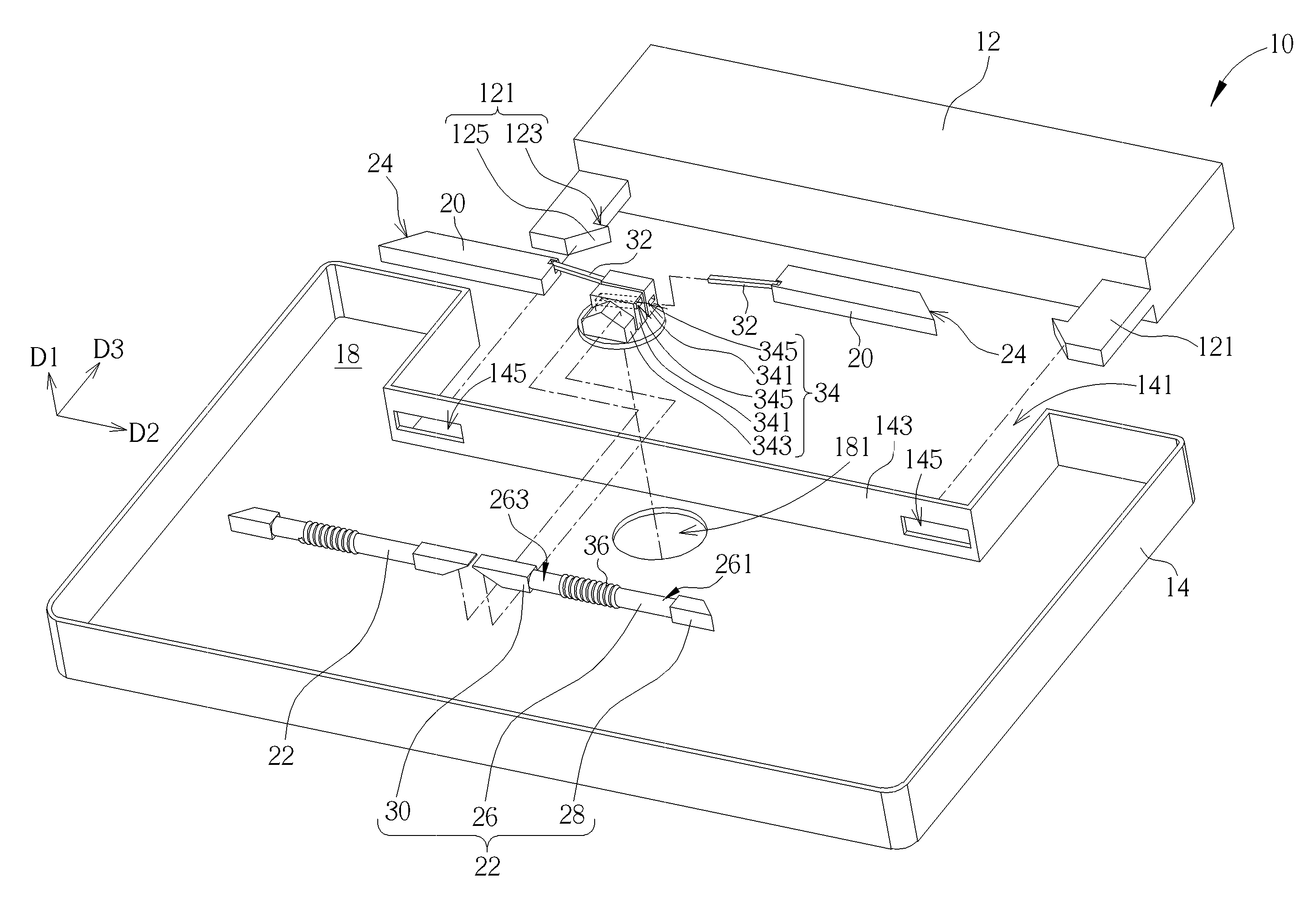
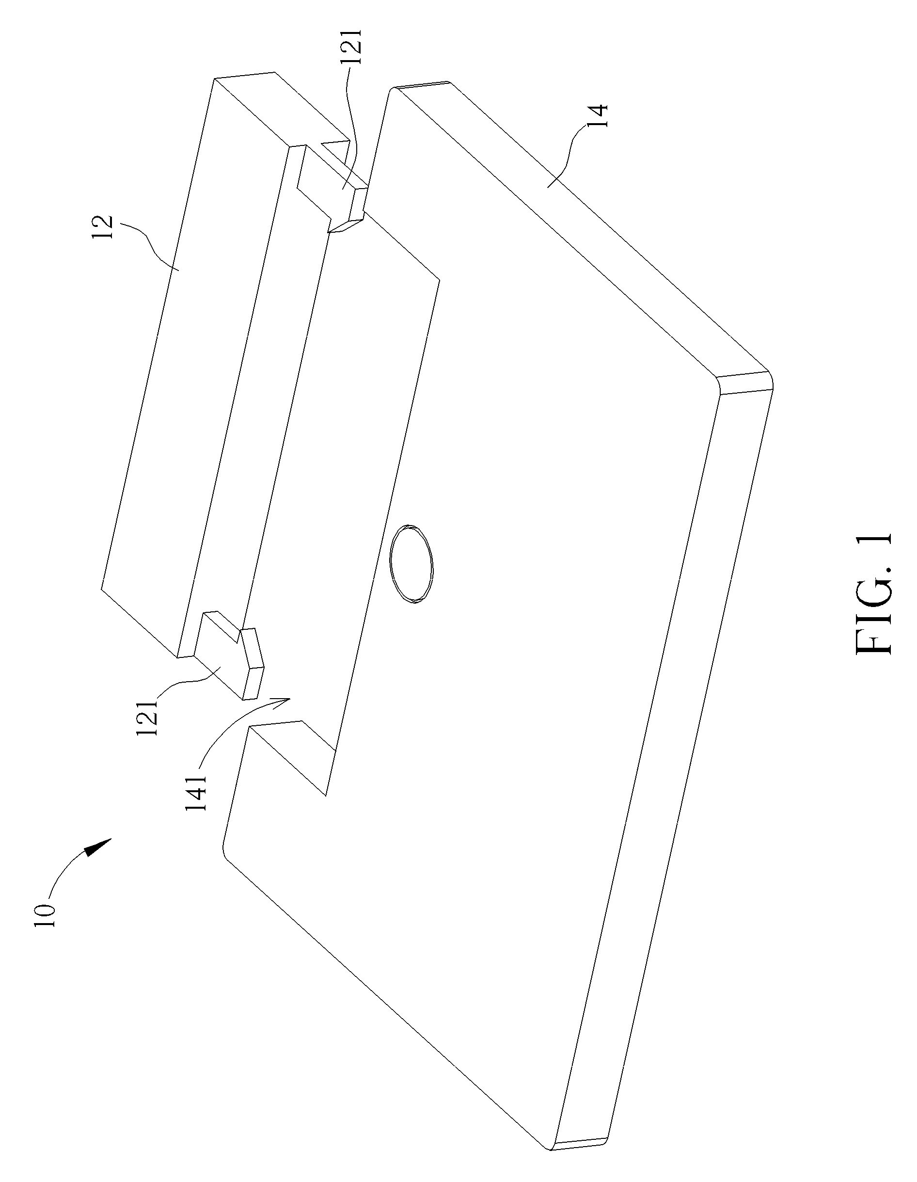
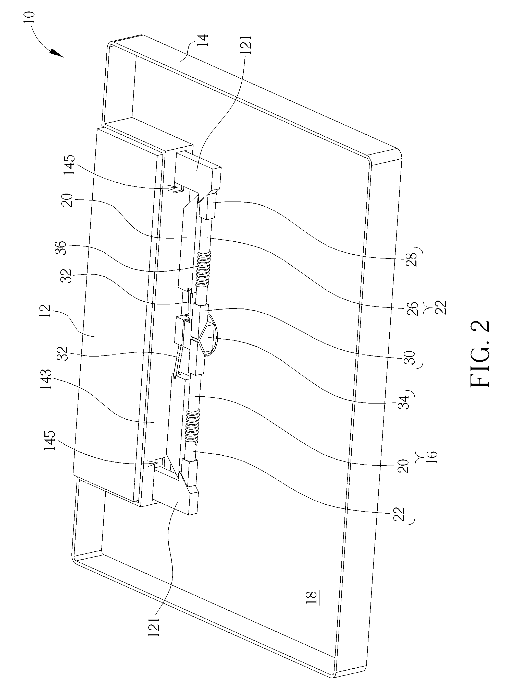
[0024]Please refer to FIG. 1 to FIG. 3. FIG. 1 and FIG. 2 respectively are diagrams of an electronic device 10 in different views according to an embodiment of the present invention. FIG. 3 is an exploded diagram of the electronic device 10 according to the embodiment of the present invention. The electronic device 10 includes an electronic component 12, a casing 14 and a lock mechanism 16. The electronic device 10 can be the notebook computer, and the electronic component 12 can be the battery to provide power energy for the notebook computer. The electronic component 12 includes two fix portions 121. The fix portions 121 can be hook structures respectively disposed on two ends of the electronic component 12. The casing 12 includes a sunken structure 141, and two opening 145 are formed on a lateral wall 143 of the sunken structure 141. The electronic component 12 can be disposed inside the sunken structure 141. Each fix portion 131 passes through the corresponding opening 145 to be...


PUM


Abstract

A lock mechanism includes a base, a constraining component, a recovering component, a bridging component and an actuating component. The constraining component contacts against a fix portion of an electronic component to constrain its movement. The recovering component includes a bar, a first inclined structure and a second inclined structure. The bar includes a first end and a second end. The first inclined structure is disposed on the first end to push the fix portion, and the second inclined structure is disposed on the second end. Two ends of the bridging component respectively connect to the constraining component and the actuating component. The actuating component movably pierces through a hole on the base to separate the constraining component from the fix portion via the bridging component, and the actuating component further pushes the second inclined structure, so as to drive the first inclined structure to outwardly move the fix portion.

Description

BACKGROUND OF THE INVENTION[0001]1. Field of the Invention[0002]The present invention relates to a lock mechanism and a related electronic device, and more particularly, to a lock mechanism and a related electronic device capable of releasing lock constraint and ejecting an electronic component simultaneously by one touch.[0003]2. Description of the Prior Art[0004]The electronic component applied to the notebook computer, such as the battery or the portable hard disk, is installed on the bottom of the notebook computer. The notebook computer is rotated to assemble and to disassemble the electronic component from the bottom of the notebook computer. Generally, the conventional latch mechanism, which is disposed on the bottom of the notebook computer, is utilized to assemble and disassemble the electronic component from a casing of the notebook computer. Operating procedure of the conventional latch mechanism is complicated and inconvenient, so quality impression and satisfaction of t...

Claims


Application Information

Patent Timeline
Patent Type & Authority Patents(United States)
IPC IPC(8): H05K5/02G06F1/16
CPCH05K5/0221G06F1/1635G06F1/1656Y10T403/602Y10T403/70
Inventor LIANG, JYUN-SHUOCHEN, HUNG-LI
Owner WISTRON CORP
Why Eureka
Try Eureka