
Backlight module and feedback circuit structure thereof

a backlight module and circuit structure technology, applied in the direction of lighting and heating apparatus, electrical apparatus casings/cabinets/drawers, instruments, etc., can solve the problems of inability to precisely control each ccfl, and interference between neighboring cold cathode fluorescent tubes, etc., to achieve the effect of boosting product competen

Active Publication Date: 2007-02-06
NYTELL SOFTWARE LLC
View PDF5 Cites 0 Cited by
  • Summary
  • Abstract
  • Description
  • Claims
  • Application Information

AI Technical Summary

Benefits of technology

"The present invention is about a feedback circuit structure and a backlight module that can switch between independent feedback and common ground feedback. This allows for more design variations and improves product competence in the market. The feedback circuit structure includes a substrate, tube contacts, independent feedback contacts, and a common feedback contact. The backlight module comprises a plurality of lamp tubes, a driving module, and the feedback circuit structure. The feedback circuit structure allows for individual or common feedback control of the lamp tubes, depending on the needs. The invention provides circuits for executing independent feedback control and common ground feedback control, saving time and money while improving display quality."

Problems solved by technology

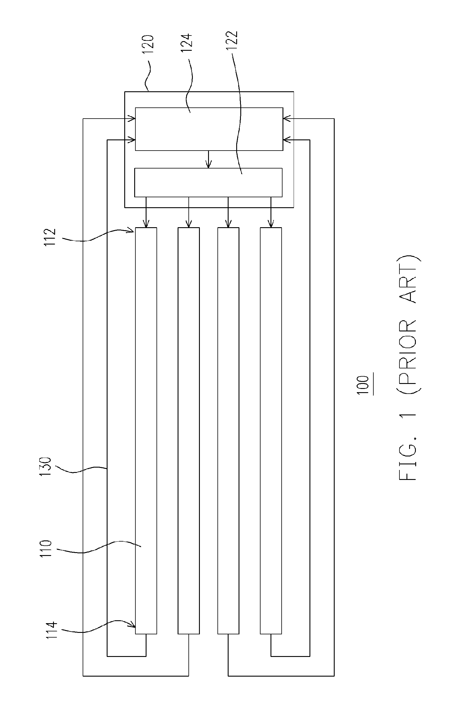
Hence, the circuit is more complicated and costly to fabricate.
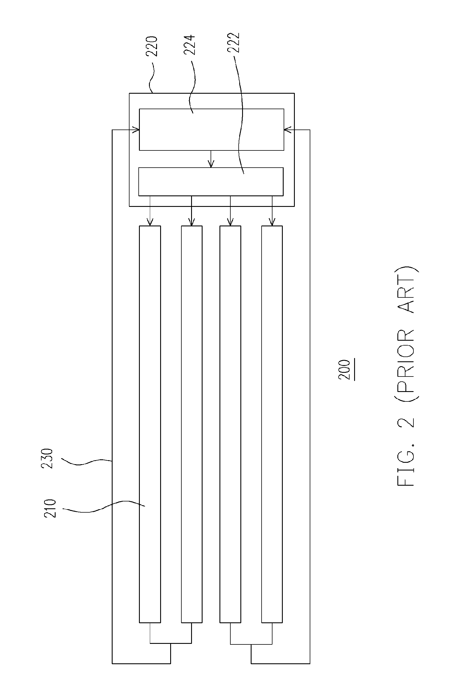
Although the common ground feedback method is able to lower the production cost and simplify the feedback circuits, the detected feedback current is that of a group of CCFL and hence precise control of each CCFL is impossible.
Furthermore, interference between neighboring cold cathode fluorescent tubes is also possible.

Method used


Image

  • Backlight module and feedback circuit structure thereof
  • Backlight module and feedback circuit structure thereof
  • Backlight module and feedback circuit structure thereof

Examples


Embodiment Construction

[0024]Reference will now be made in detail to the present preferred embodiments of the invention, examples of which are illustrated in the accompanying drawings. Wherever possible, the same reference numbers are used in the drawings and the description to refer to the same or like parts.

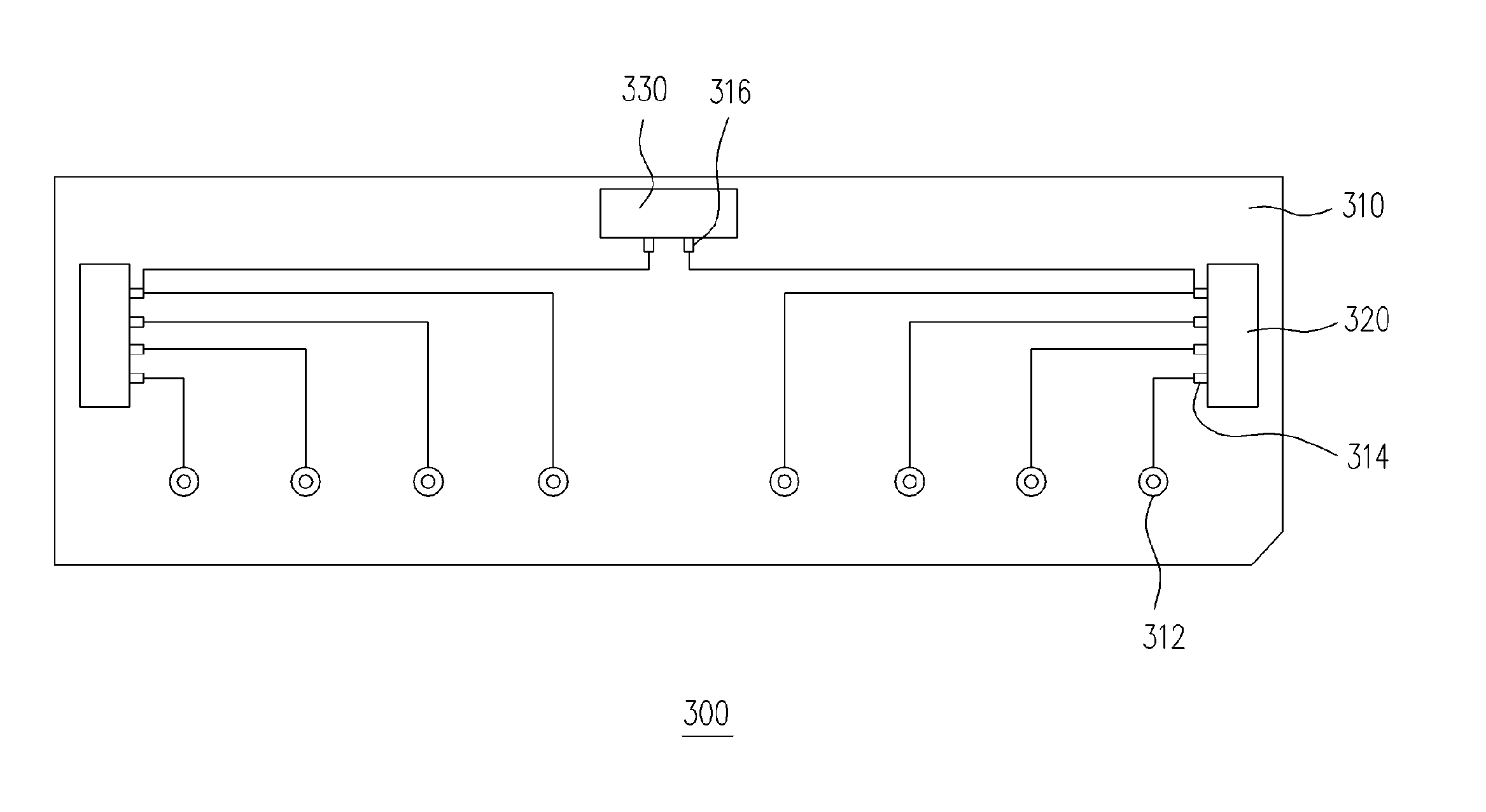
[0025]FIG. 3 is a schematic circuit diagram of a feedback circuit structure of a backlight module according to one embodiment of the present invention. As shown in FIG. 3, the feedback circuit structure 300 comprises a substrate 310, a plurality of independent feedback plugging stands 320 and a common ground feedback plugging stand 330. The substrate 310 has a plurality of tube contacts 312, a plurality of independent feedback contacts 314 and a plurality of common ground feedback contacts 316. The tube contacts 312 are used for connecting with the feedback terminals (not shown) of a plurality of cold cathode fluorescent lamps (CCFL). The independent feedback contacts 314 are coupled to the independe...


PUM


Abstract

A backlight module and a feedback circuit structure thereof are provided. The backlight module comprises a plurality of tubes, a driving module, and the feedback circuit structure. The feedback circuit structure comprises a substrate, a plurality of tube contacts, a plurality of independent feedback contacts and at least a common feedback contact. The tube contacts, the independent feedback contacts and the common feedback contact are disposed on the substrate. Each independent feedback contact is electrically connected to one of the tube contacts. The common feedback contact is electrically connected to one of the independent feedback contacts. An independent feedback can proceed by transmitting feedback signals from each independent feedback contact to a corresponding lamp tube. A common feedback can proceed by first coupling the independent feedback contacts together and then transmitting feedback signals from the common feedback contact to a multiple of lamp tubes.

Description

BACKGROUND OF THE INVENTION[0001]1. Field of the Invention[0002]The present invention relates to a backlight module and circuit structure thereof. More particularly, the present invention relates to a multi-tube backlight module and feedback circuit structure thereof.[0003]2. Description of Related Art[0004]With the rapid development of electronic industry, electronic products including mobile phones, digital cameras, digital camcorders, notebook computers, desktop computers are striving towards easier operation, more powerful functions and a better appearance. However, all these mobile phones, digital cameras, digital camcorders, notebook computers and desktop computers demand a suitable display screen to serve as a man-machine interface and facilitate various operations. In recent years, liquid crystal display (LCD) panels have become the mainstream display screens for most of the mobile phones, digital cameras, digital camcorders, notebook computers and desktop computers. Because...

Claims


Application Information

Patent Timeline
Patent Type & Authority Patents(United States)
IPC IPC(8): H05K5/00H01J9/36H05B37/00
CPCG09G3/3406H05B41/282G02F1/133604Y02B20/183G09G2320/064Y02B20/00
Inventor CHANG, CHING-LUNGWANG, YAO-TUNG
Owner NYTELL SOFTWARE LLC
Learn More