
Method for moving and aligning heavy device

a technology of heavy equipment and moving parts, applied in the field of methods, can solve the problems of falling and destroying equipment, injuring persons beneath, and not only dangerous but time-consuming operations

Active Publication Date: 2015-05-19
NUOVO PIGNONE TECH SRL
View PDF46 Cites 123 Cited by
  • Summary
  • Abstract
  • Description
  • Claims
  • Application Information

AI Technical Summary

Benefits of technology

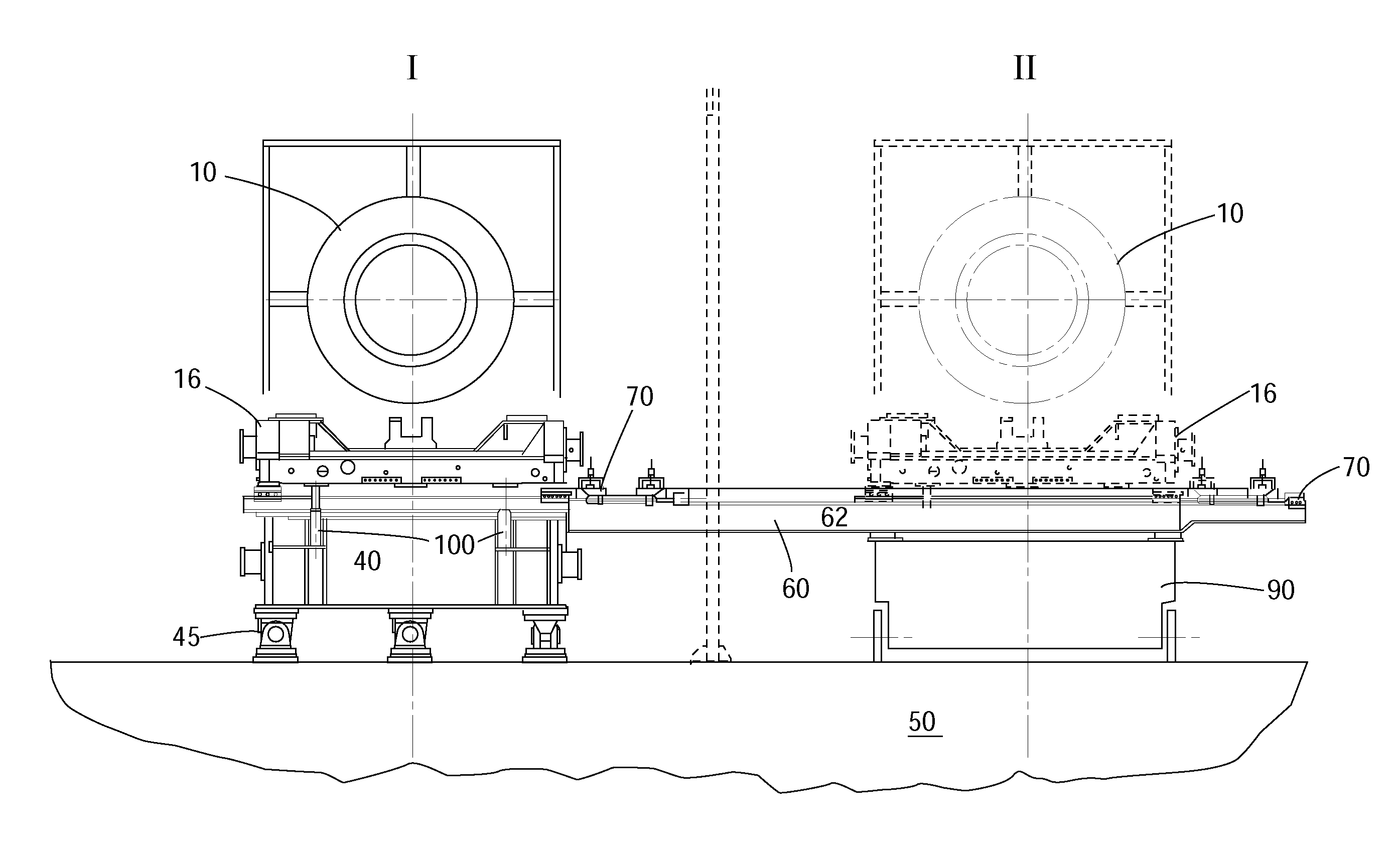
The patent text describes methods for replacing and aligning heavy components in a plant assembly. The methods involve using a lifting system to disconnect and lift the heavy component, connecting rails to the plant assembly, lowering the heavy component using crawling mechanisms, and aligning it with other components using guiding pins and moving cylinders. The patent also describes a turbine package that includes a turbine and skid for support, along with guiding pins and a single guiding pin for alignment. The technical effects of the patent text include improved efficiency and safety in the replacement and alignment of heavy components in plant assemblies.

Problems solved by technology

Thus, when performing maintenance for these heavy devices, large and powerful cranes have to be available in order to remove, for example, the casing of the turbine for various maintenance operations.
Such operations are not only dangerous but also time consuming.
In addition, the process is dangerous because heavy parts are hanging above the turbine and generator, with the potential of falling and destroying the equipment or injuring the persons beneath.
Further, as the power plant is off-shore, i.e., floating on a barge, the movement of the sea also contributes to the increase danger of having heavy devices hanging overhead.

Method used


Image

  • Method for moving and aligning heavy device
  • Method for moving and aligning heavy device
  • Method for moving and aligning heavy device

Examples


Embodiment Construction

[0030]The following description of the exemplary embodiments refers to the accompanying drawings. The same reference numbers in different drawings identify the same or similar elements. The following detailed description does not limit the invention. Instead, the scope of the invention is defined by the appended claims. The following embodiments are discussed, for simplicity, with regard to the terminology and structure of a gas turbine connected to a generator to form a plant assembly on a barge. However, the embodiments to be discussed next are not limited to these systems, but may be applied to other plant assemblies that include heavy devices that require easy and safe access and also a good alignment among the various devices. The exemplary embodiments also apply to devices that are located on the ground.

[0031]Reference throughout the specification to “one embodiment” or “an embodiment” means that a particular feature, structure, or characteristic described in connection with a...


PUM

PropertyMeasurementUnit
weightaaaaaaaaaa
weightsaaaaaaaaaa
widthaaaaaaaaaa

Abstract

Method for laterally replacing a heavy component of a plant assembly, the method including disconnecting the heavy component from other components of the plant assembly and from a base plate to which the heavy component is fixed; lifting the heavy component above the base plate with a lifting system provided within the base plate; connecting at least a pair of rails to the base plate, under the lifted heavy component, such that the at least a pair of rails extends at substantially a right angle relative to a longitudinal axis of the heavy component; lowering the heavy component on crawling mechanisms disposed on the at least a pair of rails; and laterally replacing the heavy component from the base plate and the other components of the plant assembly by actuating the crawling mechanisms.

Description

RELATED APPLICATIONS[0001]This application is related to, and claims priority from, U.S. Provisional Patent Application Ser. No. 61 / 122,106 filed on Dec. 12, 2008, entitled “Method for Moving and Aligning Heavy Device”, the disclosure of which is incorporated here by reference.BACKGROUND[0002]1. Technical Field[0003]Embodiments of the subject matter disclosed herein generally relate to methods and systems and, more particularly, to mechanisms and techniques for moving a heavy device and aligning it with other devices.[0004]2. Discussion of the Background[0005]During the past years, an increased interest in alternative sources of energy has driving the oil and gas industry in exploring fossil fuels off-shore, at higher depths. One such fossil source is liquefied natural gas (LNG). LNG is a gas that has been converted to liquid form for ease of storage or transport. Liquefied natural gas takes up about 1 / 600th the volume of natural gas at a stove burner tip. However, for the extractio...

Claims


Application Information

Patent Timeline
Patent Type & Authority Patents(United States)
IPC IPC(8): B23P11/00B23P21/00B62D65/02B66F19/00F01D25/28
CPCF01D25/28B66F19/00Y02T50/671B62D65/022B23P21/00H02K15/00H02K15/0006H02K15/02Y02T50/60Y10T29/49318Y10T29/49815Y10T29/49819Y10T29/49829B65G7/02B66F11/00
Inventor FRASSINELLI, LUCAROSSIN, STEFANOMEIATTINI, DANIELA
Owner NUOVO PIGNONE TECH SRL
Learn More