Device, system and method for in-situ drill guide sleeve orientation

Inactive Publication Date: 2015-05-12
NAVIDENT MEDICAL DEVICE
View PDF7 Cites 11 Cited by
  • Summary
  • Abstract
  • Description
  • Claims
  • Application Information

AI Technical Summary

Benefits of technology

The present invention provides a device, system, and method for facilitating the determination of a drill path over the entire edentulous area where an implant procedure is to take place. The device allows a practitioner to determine the orientation and position of a drill guide sleeve over the entire edentulous area with full range and continuous motion in about both the buccal-lingual axis and the mesio-distal axis, allowing the practitioner to identify the optimal orientation and / or location for the drill path according to the clinical situation at hand. The device provides at least five degrees of freedom in orienting and / or maneuvering a sleeve within the device's housing and over the edentulous area, corrective measures may also be applied, for example, by providing a replaceable orientation device that may be associated or disassociated with a guide mold. The sleeve manipulating tool may further facilitate associating or disassociating the orientation device with the guide mold.

Problems solved by technology

While this determination is done on the basis of the clinician's knowledge and practice and aided with medical imagery, however, the drill guide itself is generally prepared by a technician and not by the implanting practitioner, therefore lending itself to human error.
More over inherent errors in the medical imagery devices, giving an error of about 10%, leads to further error in determining the location of the sleeve within the drill guide.
However such errors are usually not identified until the onset of the implant procedure, itself where a mismatch between the drill guide and the clinical situation before an implanting practitioner is realized.
Most drill guides are limited in that once the template is made its configuration cannot be further adjusted.
However both Stumpel and Csillag are limited in the range of motion they offer over the edentulous area, specifically they do not provide a full range of motion over the edentulous area.

Method used


Image

  • Device, system and method for in-situ drill guide sleeve orientation
  • Device, system and method for in-situ drill guide sleeve orientation
  • Device, system and method for in-situ drill guide sleeve orientation

Examples


Embodiment Construction

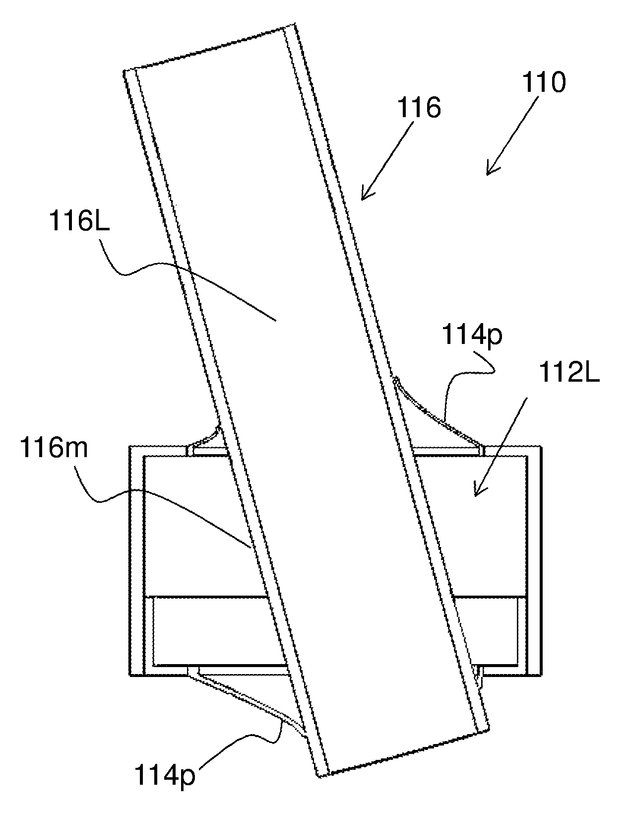
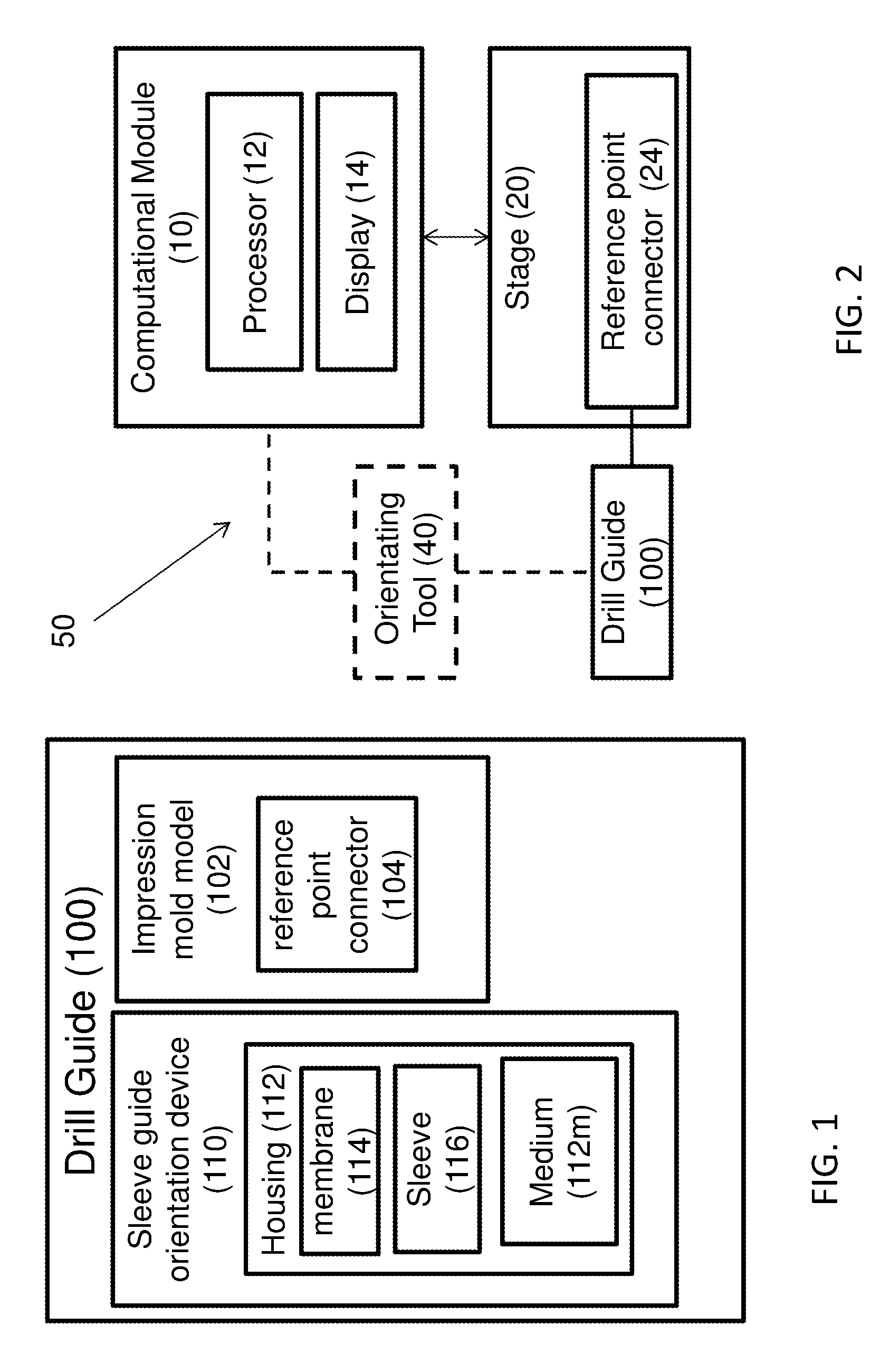
[0060]The present invention is of a device, system and method for positioning and orienting a drill guide sleeve within a drill guide to determine the drill path over an edentulous site. Preferably embodiments provide for determining the orientation of the drill guide sleeve in a chair-side manner allowing the implanting clinician to accurately determine the drill path in situ therein taking into account the clinical situation at hand.

[0061]The principles and operation of the present invention may be better understood with reference to the drawings and the accompanying description. The following figure reference labels are used throughout the description to refer to similarly functioning components are used throughout the specification hereinbelow.[0062]10 computational module;[0063]12 processor;[0064]14 display;[0065]20 drill guide coupling stage;[0066]24 reference point connectors;[0067]40 dedicated orientation tool;[0068]42 manual orientation tool;[0069]45 automated orientation t...


PUM


Abstract

The present invention relates to a device, system and method for producing a dental implant drill guide and in particular to such a device system and method for positioning a sleeve within a drill guide to determine the drill path for positioning a dental implant at an implantation site over the entire edentulous site where the sleeve may be fixed in its position and orientation anywhere about the edentulous area having full range of motion thereabout, while the sleeve orientation may be fixed by introduction of a curing agent.

Description

RELATED APPLICATIONS[0001]This utility patent application claims priority from U.S. Provisional Application No. 61 / 693,345 filed on 27 Aug. 2012, the contents of which are fully incorporated herein as if fully set forth.FIELD OF THE INVENTION[0002]The present invention relates to a device, system and method for producing a dental implant drill guide and in particular to such a device system and method for positioning a sleeve within a drill guide to determine the drill path for positioning a dental implant at an implantation site over an edentulous site.BACKGROUND OF THE INVENTION[0003]Dental implants are well known in the art and typically include a dental anchor securely inserted into the patient's jawbone, and an abutment member mountable to the dental anchor, the abutment utilized for coupling a restoration.[0004]One of the initial steps in the implantation process and perhaps the most crucial step is determining where to place the implant anchor within the jawbone over the eden...

Claims


Application Information

Patent Timeline
IPC IPC(8): A61C3/04A61C1/08A61C8/00A61C13/15
CPCA61C1/084A61C19/003A61C8/0089
Inventor SHABAT, RONI
Owner NAVIDENT MEDICAL DEVICE
Why Eureka
Try Eureka