
In-vehicle internal combustion engine control device, and control method for internal combustion engine

a control device and internal combustion engine technology, applied in the direction of engine-driven generators, machine/engine control, process and machine control, etc., can solve the problems of increasing the magnitude of vibration transmitted to the vehicle body, increasing the magnitude of vibration, and affecting the performance of the engine, so as to reduce the transmission of vibrations, reduce the degree of deformation of the mount, and reduce the effect of vibration transmission

Active Publication Date: 2015-05-05
TOYOTA JIDOSHA KK +1
View PDF9 Cites 2 Cited by
  • Summary
  • Abstract
  • Description
  • Claims
  • Application Information

AI Technical Summary

Benefits of technology

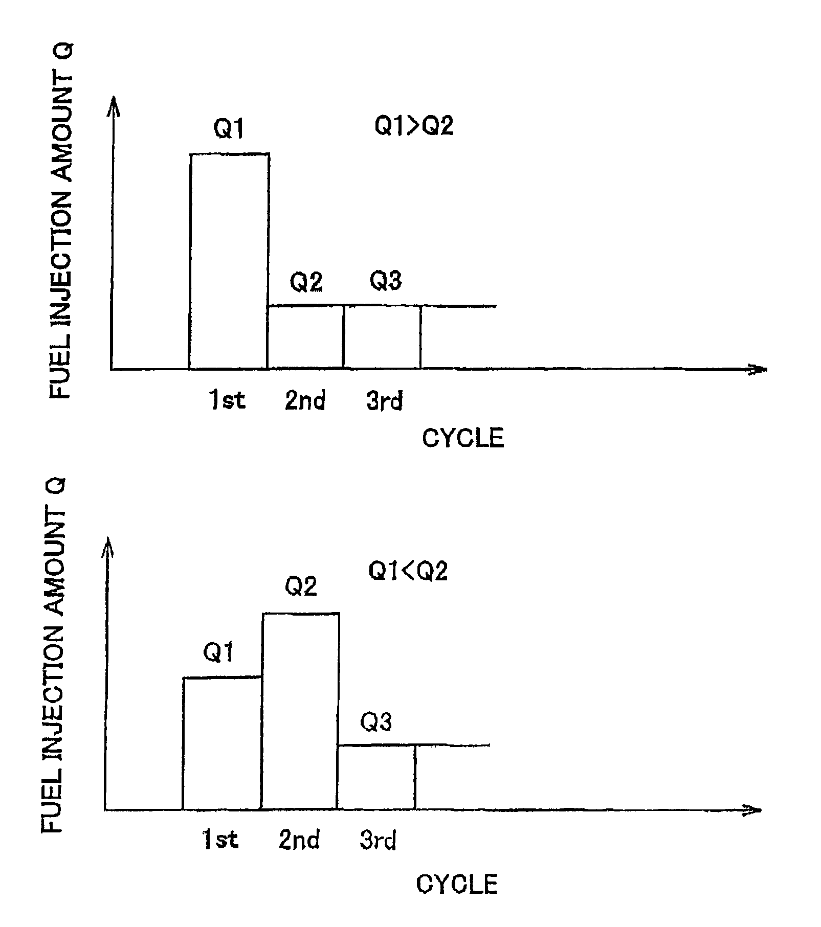
The invention provides a device and method for controlling an internal combustion engine in a vehicle while driving. The device detects the degree of deformation of the mount that connects the engine to the vehicle and adjusts the fuel injection amount accordingly to reduce the transmission of vibrations to the vehicle and initial discomfort for the driver during engine start-up. This results in a comfortable driving experience for the driver.

Problems solved by technology

However, when the control device of the above described HV starts the engine while the vehicle is driving, if the first-cycle fuel injection amount is set so as to be larger than the second and the following-cycle fuel injection amounts, the power of the engine steeply varies with combustion of fuel injected in the first cycle to increase the magnitude of vibrations transmitted to the vehicle body.
This makes a driver experience a significant uncomfortable feeling.
Thus, as the time interval between vibrations due to cranking and vibrations due to combustion of fuel injected in the second cycle extends, driver's uncomfortable feeling may become more significant.

Method used


Image

  • In-vehicle internal combustion engine control device, and control method for internal combustion engine
  • In-vehicle internal combustion engine control device, and control method for internal combustion engine
  • In-vehicle internal combustion engine control device, and control method for internal combustion engine

Examples


Embodiment Construction

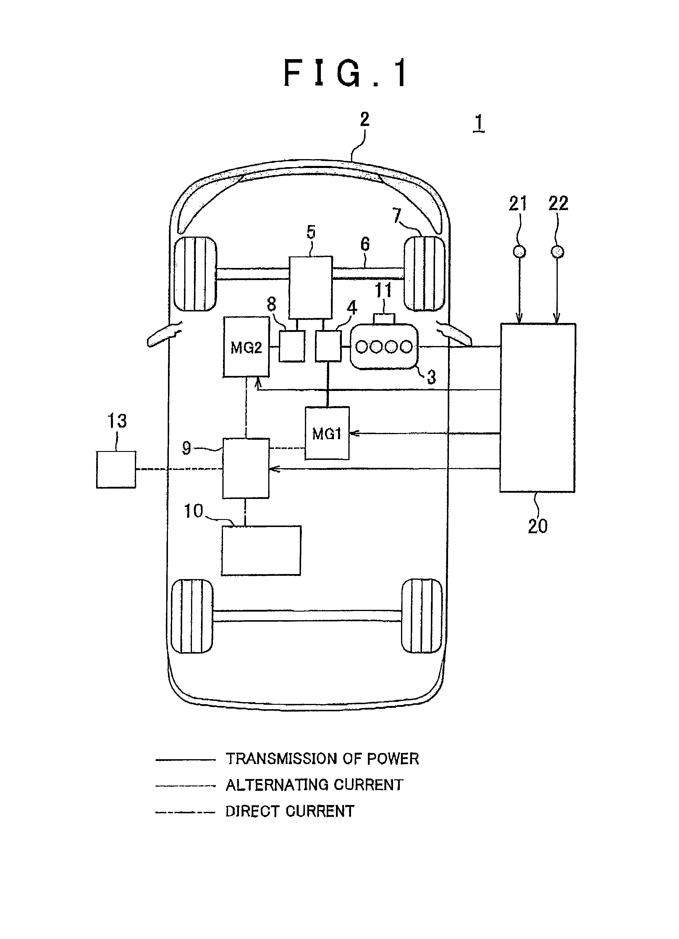
[0033]Hereinafter, a specific embodiment in which an in-vehicle internal combustion engine control device according to the aspect of the invention is applied to a control device of a hybrid vehicle (hereinafter, referred to as vehicle) 1 will be described in detail with reference to FIG. 1 to FIG. 7.

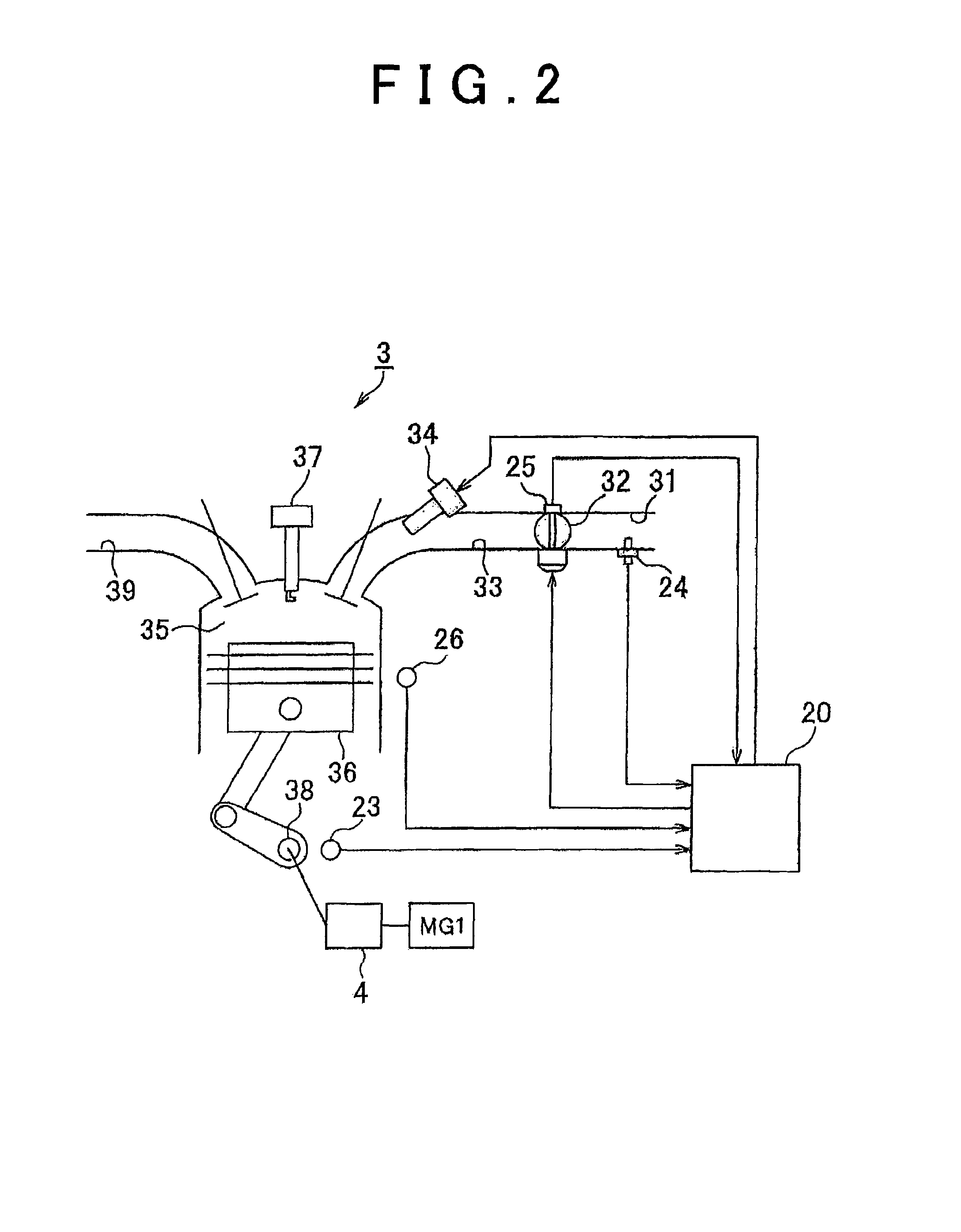
[0034]FIG. 1 shows the schematic configuration of the vehicle according to the present embodiment. FIG. 2 schematically shows the cross-sectional structure of an internal combustion engine according to the present, embodiment. Note that FIG. 2 shows the cross-sectional structure of one of cylinders.

[0035]As shown in FIG. 1, the vehicle includes the internal combustion engine 3 and a motor generator (hereinafter, referred to as second motor generator) MG2 as power sources that rotate drive wheels 7. Specifically, the vehicle 1 according to the present embodiment is a so-called plug-in hybrid vehicle (hereinafter, referred to as PHV) of which a battery 10 is chargeable from an external pow...


PUM


Abstract

At the time of an engine start while the vehicle is driving, when a required vehicle driving force (TRQ) is smaller than or equal to a predetermined value (TRQth), an electronic control unit (20) estimates that the degree of deformation of a mount (11) is smaller than or equal to a predetermined degree and sets a second-cycle fuel injection amount (Q2) so as to be larger than a first-cycle fuel injection amount (Q1) at the time of the engine start. On the other hand, when the required vehicle driving force (TRQ) is larger than the predetermined value (TRQth), the electronic control unit (20) estimates that the degree of deformation of the mount (11) is larger than the predetermined degree and sets the first-cycle fuel injection amount (Q1) so as to be larger than the second-cycle fuel injection amount (Q2) at the time of the engine start.

Description

BACKGROUND OF THE INVENTION[0001]1. Field of the Invention[0002]The invention relates to an in-vehicle internal combustion engine control device and a control method for am internal combustion engine, which are applied to a vehicle equipped with an internal combustion engine and another power source, other than the internal combustion engine, as devices that transmit power to a drive wheel, and which start the engine while the vehicle is driving.[0003]2. Description of Related Art[0004]An in-vehicle internal combustion engine control device of this type is for example, described in Japanese Patent Application Publication No. 2009-281260 (JP-A-2009-281260). General in-vehicle internal combustion engine control devices, including the one described in JP-A-2009-281260, control a vehicle equipped with both an internal combustion engine and an electric motor as power sources for rotating the drive wheels of the vehicle, that is, a so-called hybrid vehicle (hereinafter, simply referred to...

Claims


Application Information

Patent Timeline
Patent Type & Authority Patents(United States)
IPC IPC(8): F02D41/32B60K6/445B60K6/448B60L50/16B60W10/06B60W20/00B60W30/192B60W30/20F02D41/02F02D41/06F02D41/14
CPCF02D41/32B60K6/448B60W10/06B60W20/00B60W30/192B60W30/20F02D41/0215F02D41/061F02D41/064F02D41/1498B60K6/445B60W2540/10B60W2710/0627B60W2710/0672F02D41/065F02D2250/28Y02T10/6243Y02T10/6269Y02T10/6239Y02T10/62B60W40/10
Inventor YAMAMOTO, MASAYAFUNADA, MASASHI
Owner TOYOTA JIDOSHA KK
Learn More