Eureka AIR delivers breakthrough ideas for toughest innovation challenges, trusted by R&D personnel around the world.

Marine propulsion-and-control system implementing articulated variable-pitch propellers

a technology of variable pitch propellers and propulsion control systems, applied in the field of dual-propeller-based systems, can solve the problems of limited maneuverability and thrust vectoring capability, and the use of additional or alternative devices, such as thruster groups and moveable propulsor pods, is also limited in same or similar respects

Active Publication Date: 2015-05-05
THE UNITED STATES OF AMERICA AS REPRESENTED BY THE SECRETARY OF THE NAVY
View PDF19 Cites 19 Cited by
  • Summary
  • Abstract
  • Description
  • Claims
  • Application Information

AI Technical Summary

Benefits of technology

The present invention introduces a new way to articulate two propellers in a Haselton-type configuration, which allows marine vehicles to move in six degrees of freedom. This innovation leads to improved maneuverability and control of small-to-medium sized unmanned underwater vehicles (UUVs). With the inventive system, UUVs can achieve precision station keeping, variable-angle vehicle positioning, and translation independent of orientation while maintaining efficient cruising at speed. This is a technology that can enable missions that were previously unimaginable.

Problems solved by technology

A Haselton-type propulsion-and-control system, as is currently known, utilizes tandem fore-and-aft coaxial contra-rotating propellers that are variable in blade pitch but are otherwise fixed, that is, are “non-articulated.” Although traditional Haselton propulsors afford some degree of multi-axis control, they are limited in their maneuverability and thrust-vectoring capability.
The use of additional or alternative devices, such as thruster groups and moveable propulsor pods, is also limited in same or similar respects.

Method used


Image

  • Marine propulsion-and-control system implementing articulated variable-pitch propellers
  • Marine propulsion-and-control system implementing articulated variable-pitch propellers
  • Marine propulsion-and-control system implementing articulated variable-pitch propellers

Examples


Embodiment Construction

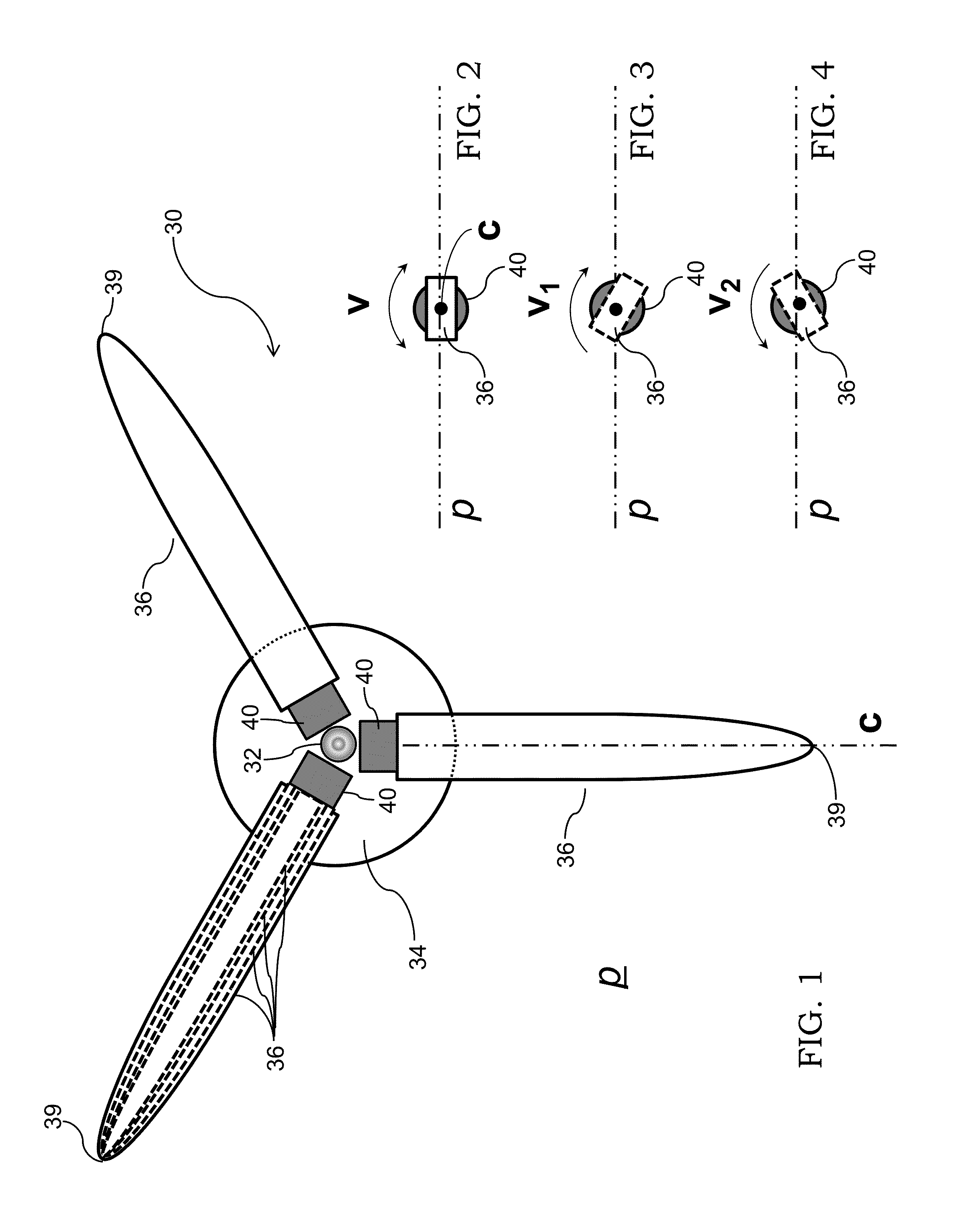
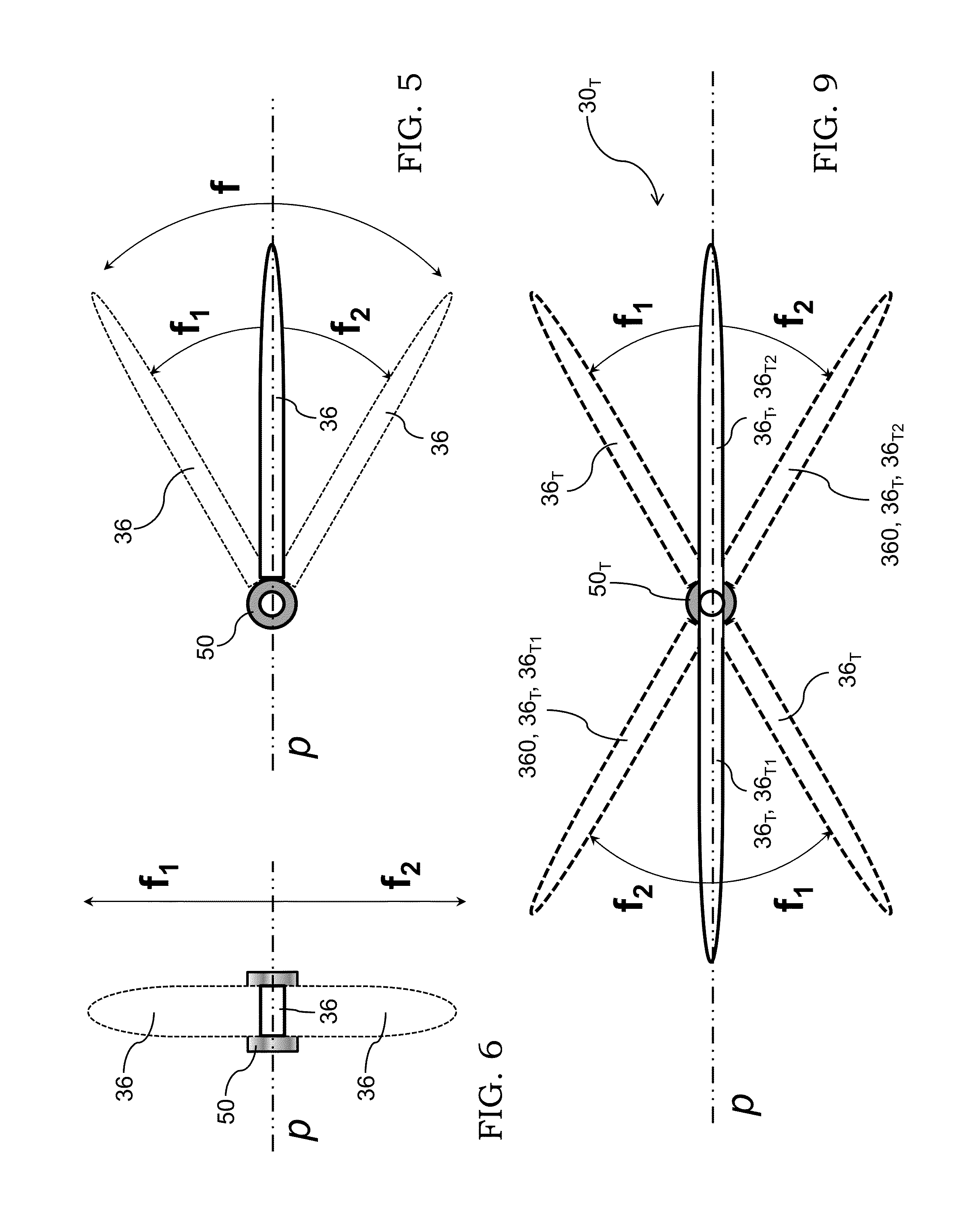
[0024]Referring now to the figures and particularly to FIGS. 1, 7, and 8, three-bladed propeller 30 includes a propeller shaft 32, a propeller hub 34, and three propeller blades 36. Each blade 36 has a blade tip 39. Blades 36 are arranged symmetrically about the central hub 34 in a generally coplanar manner so as to approximately define a geometric plane p that is perpendicular to shaft 32. Each blade 36 is generally characterized by a geometric longitudinal axis c that generally lies in geometric plane p, which generally describes the geometric rotational plane of propeller 30. Plane p represents the “zero-angle tip-path plane”—i.e., the geometric plane in which normally lies the path of the blade tips 39.

[0025]The depictions herein of propellers are diagrammatic and are not intended to convey specificity or preference with regard to blade shapes and other geometric aspects of propellers. The skilled artisan who reads the instant disclosure will appreciate that inventive principles...


PUM


Abstract

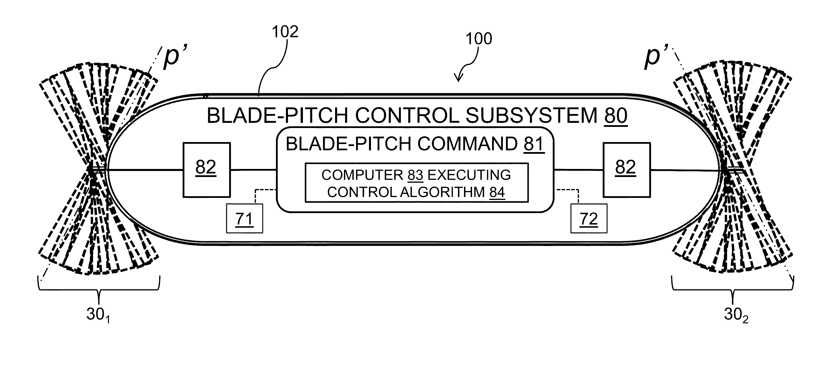
According to typical inventive practice, a cylindrical or prolate spheroidal marine hull has two congruent contra-rotative propellers coaxially situated at or near its axial ends. Each propeller has plural blades mechanically and / or flexibly attributed with changeability of blade pitch angles and blade flap angles. A blade-pitch control system adjusts the individual blade pitch angles of both propellers. The blade-pitch control system may be electronically and / or mechanically actuated, and is capable of: (i) cyclically adjusting the blade pitch angles of the two propellers so as to select two respective blade-tip-path planes, each characterized by a direction of thrust that is associated with the blade flap angles and is generally perpendicular to the blade-tip-path plane; (ii) collectively adjusting the blade pitch angles of the two propellers so as to select two respective magnitudes of thrust. The cyclic and collective blade commands, algorithmically coordinated, determine the direction, orientation, and speed of the hull.

Description

BACKGROUND OF THE INVENTION[0001]The present invention relates to propulsion and control of underwater vehicles, more particularly to dual-propeller-based systems for accomplishing same with regard to submersibles such as unmanned underwater vehicles (UUVs).[0002]Current methodologies for underwater propulsion and control require multiple systems in order to provide efficient cruise power and low-speed control. Conventional rigid propellers afford good thrust but poor lateral and off-axis control (i.e., control of lateral forces and moments). Conventional underwater vehicles seek to overcome such deficiencies by implementing additional devices, e.g., rudders and planes for lateral control. Rudders and planes, however, are ineffective at low speeds or while hovering. Although thrusters can be implemented to provide multi-axis control, they require axis-independent units and are not suited for high-speed or high-efficiency applications.[0003]Frederick R. Haselton introduced about fift...

Claims


Application Information

Patent Timeline
IPC IPC(8): B63G8/16B63H25/42B63H5/10B63G8/00
CPCB63G8/001B63H25/42B63G8/16B63H5/10
Inventor SILBERG, ERIC J.EVERSON, DANIELHAAS, DAVID J.
Owner THE UNITED STATES OF AMERICA AS REPRESENTED BY THE SECRETARY OF THE NAVY
Why Eureka
Eureka Blog
Learn More