Strain wave gear apparatus

a gear apparatus and strain wave technology, applied in mechanical equipment, belts/chains/gearrings, etc., can solve the problems of shortening affecting the operation of the gear, and limiting the use of the gear, so as to prolong the life of the strain wave gear apparatus, reduce the rotational moment, and transmit the torque stably

Inactive Publication Date: 2015-05-05
CANON KK
View PDF3 Cites 3 Cited by
  • Summary
  • Abstract
  • Description
  • Claims
  • Application Information

AI Technical Summary

Benefits of technology

[0008]In view of the circumstances, it is an object of the present invention to provide a strain wave gear apparatus capable of stably transmitting a torque even under high load application, and prolonging a life of the strain wave gear apparatus by reducing a rotational moment applied about a center of gravity of a wave generator.
[0010]According to the present invention, at least the part of the first contact region and at least the part of the second contact region overlap with each other as viewed in the direction orthogonal to the direction of the input rotation axis. Thus, the load torques applied to the two meshing positions of the annular rigid internal gear and the annular flexible external gear can be more equalized than in conventional structures. Therefore, the allowable load torque can be increased, and hence the load torques can be stably transmitted. In addition, the rotational moment applied about the center of gravity of the wave generator becomes lower, and hence the life of the strain wave gear apparatus can be prolonged.

Problems solved by technology

With this structure, when a load torque is applied to an output shaft, the load torque cannot be applied equally to the two meshing positions, which has hindered an increase in allowable load torque.
Therefore, when the load torque applied to the output shaft becomes higher, the rotational moment applied about the center of gravity of the wave generator also becomes higher, which has caused a problem of shortening of a life of the strain wave gear apparatus.

Method used


Image

  • Strain wave gear apparatus
  • Strain wave gear apparatus
  • Strain wave gear apparatus

Examples


first embodiment

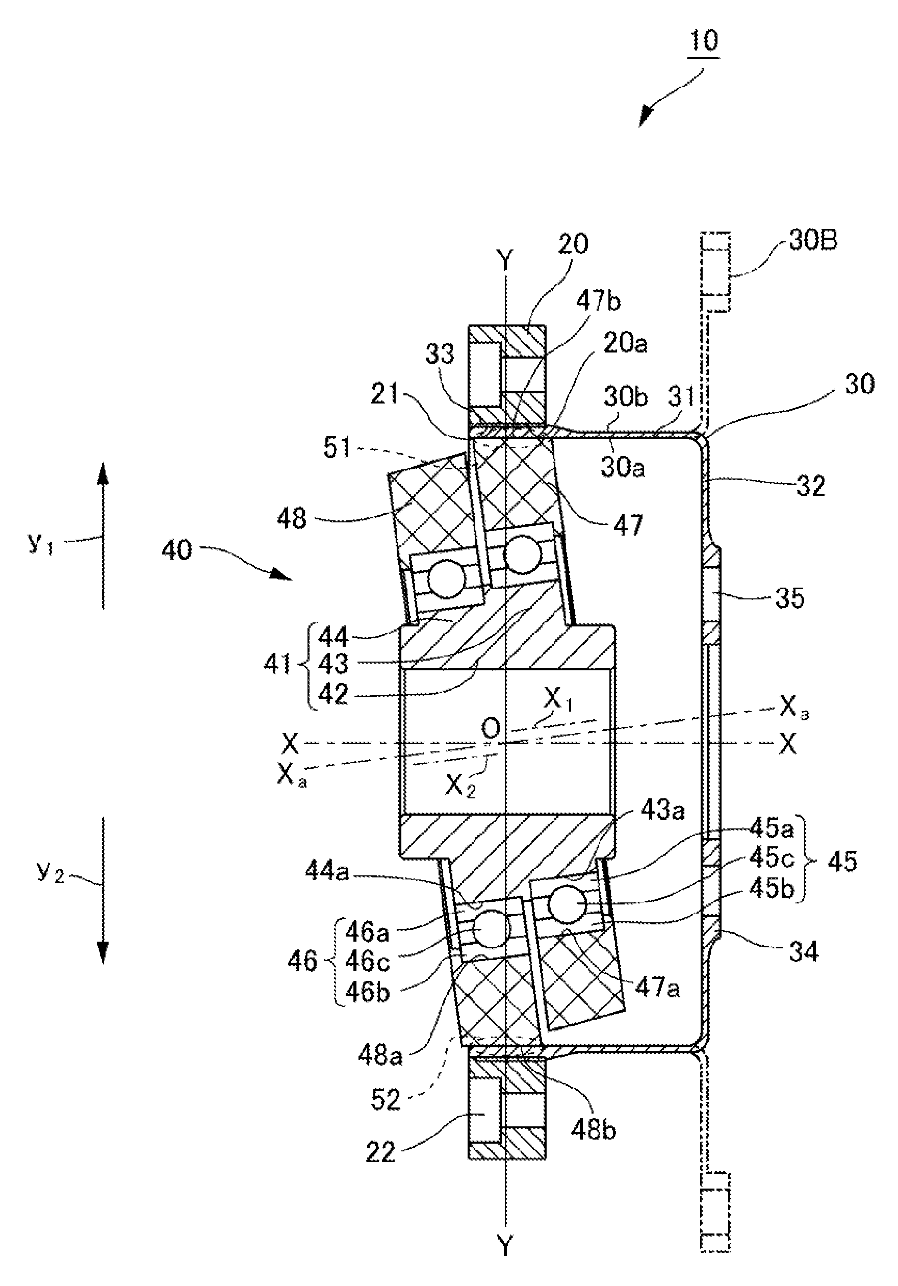
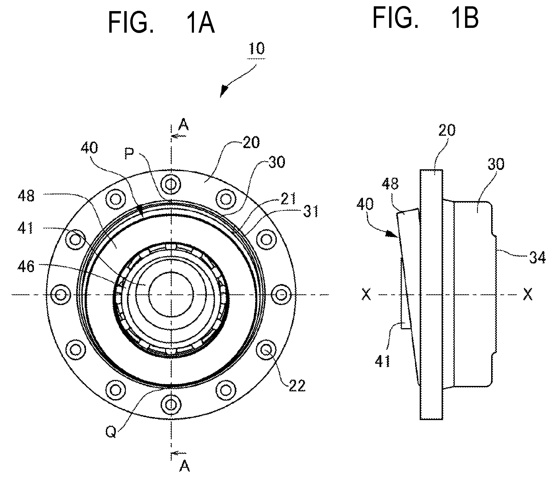
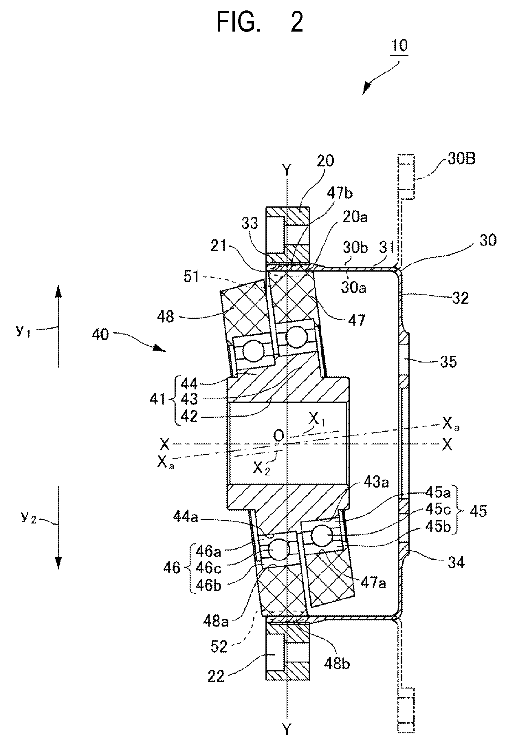
[0017]FIGS. 1A and 1B are each an explanatory view of a schematic structure of a strain wave gear apparatus according to a first embodiment of the present invention; specifically, FIG. 1A is a front view of the strain wave gear apparatus, and FIG. 1B is a side view of the strain wave gear apparatus. FIG. 2 is a sectional view of the strain wave gear apparatus, which is taken along the sectional plane A-A of FIG. 1A.

[0018]As illustrated in FIGS. 1A and 1B, a strain wave gear apparatus 10 is a strain wave gear apparatus speed reducer including a rigid internal gear 20, a flexible external gear 30, and a wave generator 40 which are arranged coaxially with an input rotation axis X-X.

[0019]The rigid internal gear 20 is formed of an annular rigid member. As illustrated in FIG. 2, the rigid internal gear 20 has an inner peripheral surface 20a provided with inner teeth 21. The rigid internal gear 20 is provided with a fixing bolt hole 22 for fixing the rigid internal gear 20 to a fixing mem...

second embodiment

[0055]Next, a strain wave gear apparatus according to a second embodiment of the present invention is described. FIG. 4 is a sectional view of the strain wave gear apparatus according to the second embodiment of the present invention. Note that, in FIG. 4, the same components as those of the strain wave gear apparatus 10 according to the first embodiment are denoted by the same reference symbols, and description thereof is omitted.

[0056]A strain wave gear apparatus 110 according to the second embodiment of the present invention is a flat strain wave gear apparatus speed reducer including an annular rigid internal gear 120, an annular flexible external gear 130, and a wave generator 40 which are arranged coaxially with the input rotation axis X-X, the wave generator 40 having the same structure as the wave generator 40 in the first embodiment described above. In other words, the wave generator 40 described above in the first embodiment is applicable also to the flat strain wave gear ...


PUM


Abstract

A strain wave gear apparatus includes a rigid internal gear, a flexible external gear, and a wave generator. The wave generator includes an input shaft fixing member including eccentric cams, bearings respectively fixed to outer sides of the eccentric cams, and housings respectively fitted to outer peripheral surfaces of the bearings. The eccentric cams are arranged side by side in a direction of an inclined axis inclined with respect to an input rotation axis at an inclination angle (θ) in a manner that respective center axes of the eccentric cams are parallel to the inclined axis and decentered in directions opposite to each other from the inclined axis. The housings are each formed into a tapered shape so that an outer peripheral surface of each of the housings is held in surface contact with an inner peripheral surface of the flexible external gear.

Description

BACKGROUND OF THE INVENTION[0001]1. Field of the Invention[0002]The present invention relates to a strain wave gear apparatus including a rigid internal gear, a flexible external gear, and a wave generator.[0003]2. Description of the Related Art[0004]In general, a strain wave gear apparatus is known as a speed reducer which is lightweight and compact, and performs speed reduction at a high speed reduction ratio in a single step. A general strain wave gear apparatus includes an annular rigid internal gear, a flexible external gear arranged on an inside of the annular rigid internal gear, and a wave generator for partially meshing the flexible external gear with the rigid internal gear at two meshing positions by deflecting the flexible external gear in a radial direction, and moving the two meshing positions in a circumferential direction.[0005]A typical conventional wave generator includes elliptical cams and elastically deformable special bearings respectively fitted into outer per...

Claims


Application Information

Patent Timeline
Patent Type & Authority Patents(United States)
IPC IPC(8): F16H49/00
CPCF16H49/001Y10T74/19
Inventor TAKAHASHI, TOSHIFUMISATO, MASAICHIOKUMA, ISAMU
Owner CANON KK
Why Eureka
Try Eureka