
Interference management in wireless communication networks

a wireless communication network and interference management technology, applied in transmission monitoring, machine-to-machine/machine-type communication services, orthogonal multiplexes, etc., can solve problems such as the increase of radio interference between devices, and achieve the effect of reducing interference in the system

Inactive Publication Date: 2015-04-28
FUJITSU LTD
View PDF12 Cites 0 Cited by
  • Summary
  • Abstract
  • Description
  • Claims
  • Application Information

AI Technical Summary

Benefits of technology

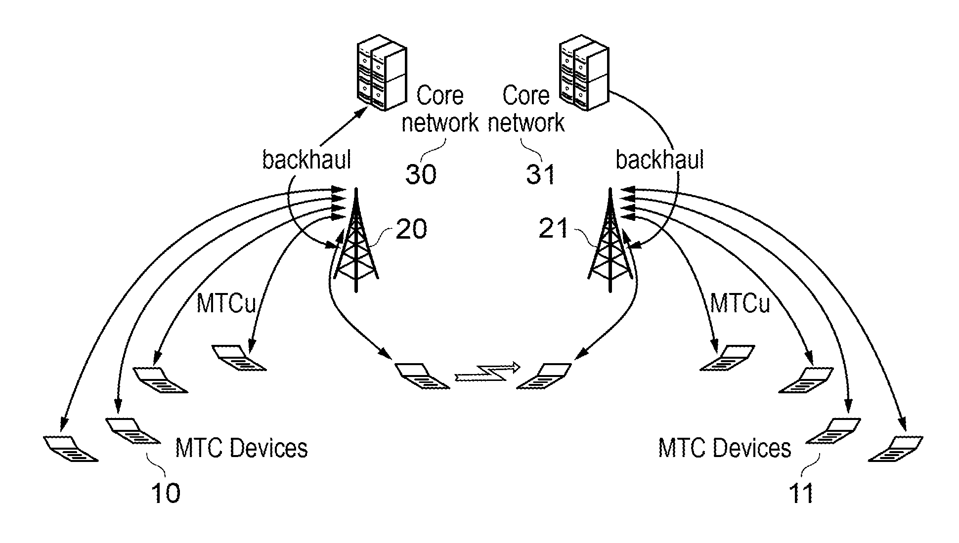
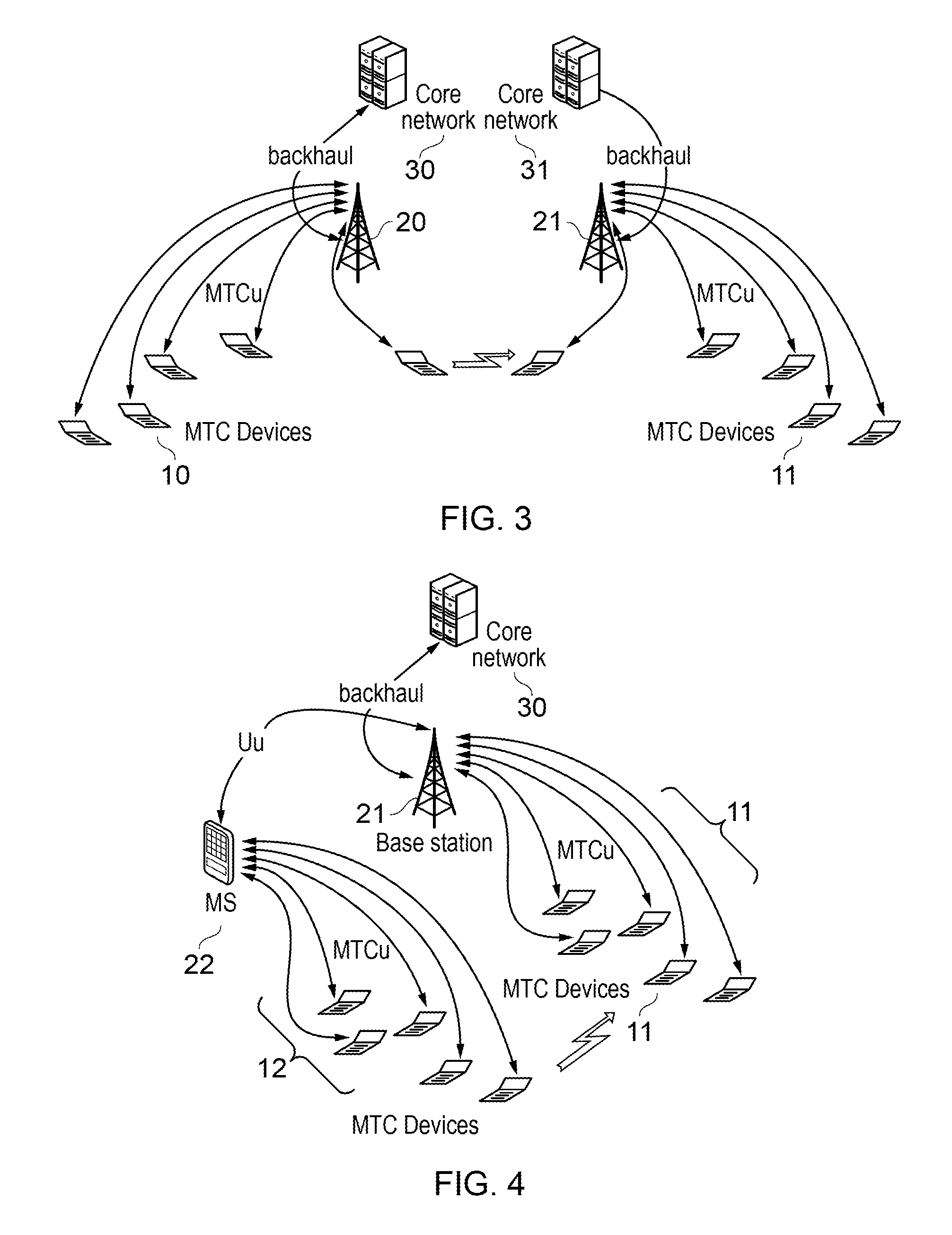
[0031]MTC is a specific use case for an embodiment of the present invention. According to an ETSI proposal, a network remote entity management (NREM) capability provides a common service platform for all the MTC devices. Thus, when at least some of the devices are MTC devices, it is preferable that the controller be associated with the NREM. The controller is preferably at the service / application level in the system; that is, at the level of MTC services or applications which make use of information gained from the MTC devices, rather than at the network level. This allows the controller to gather information from the plurality of radio access networks, which potentially implement different RATs. The controller may be part of (or constitute) an MTC server within an M2M Service Capabilities Layer.
[0033]Alternatively, or in addition, the instructions include one or more instructions to the wireless device which measured the interference. In other words, the controller instructs the interference-measuring device to alter its wireless link with a base station or hub, or any intermediate node such as a peer device in a peer-to-peer network, so as to avoid the time / frequency resources most affected by interference.
[0039]In addition, preferably, the controller is arranged to interrogate each wireless device about its capabilities for at least interference measurement. In this way, the controller is able to obtain more detailed interference reports from suitably-capable wireless devices.

Problems solved by technology

As the number of devices in a given geographical area increases, the problem of radio interference between devices will increase.
However, such management is generally confined to a single radio access network (RAN) as explained below.

Method used


Image

  • Interference management in wireless communication networks
  • Interference management in wireless communication networks
  • Interference management in wireless communication networks

Examples


Embodiment Construction

[0061]Before describing embodiments of the present invention, some further explanation will be given of interference scenarios and measures already under consideration for mitigation of interference.

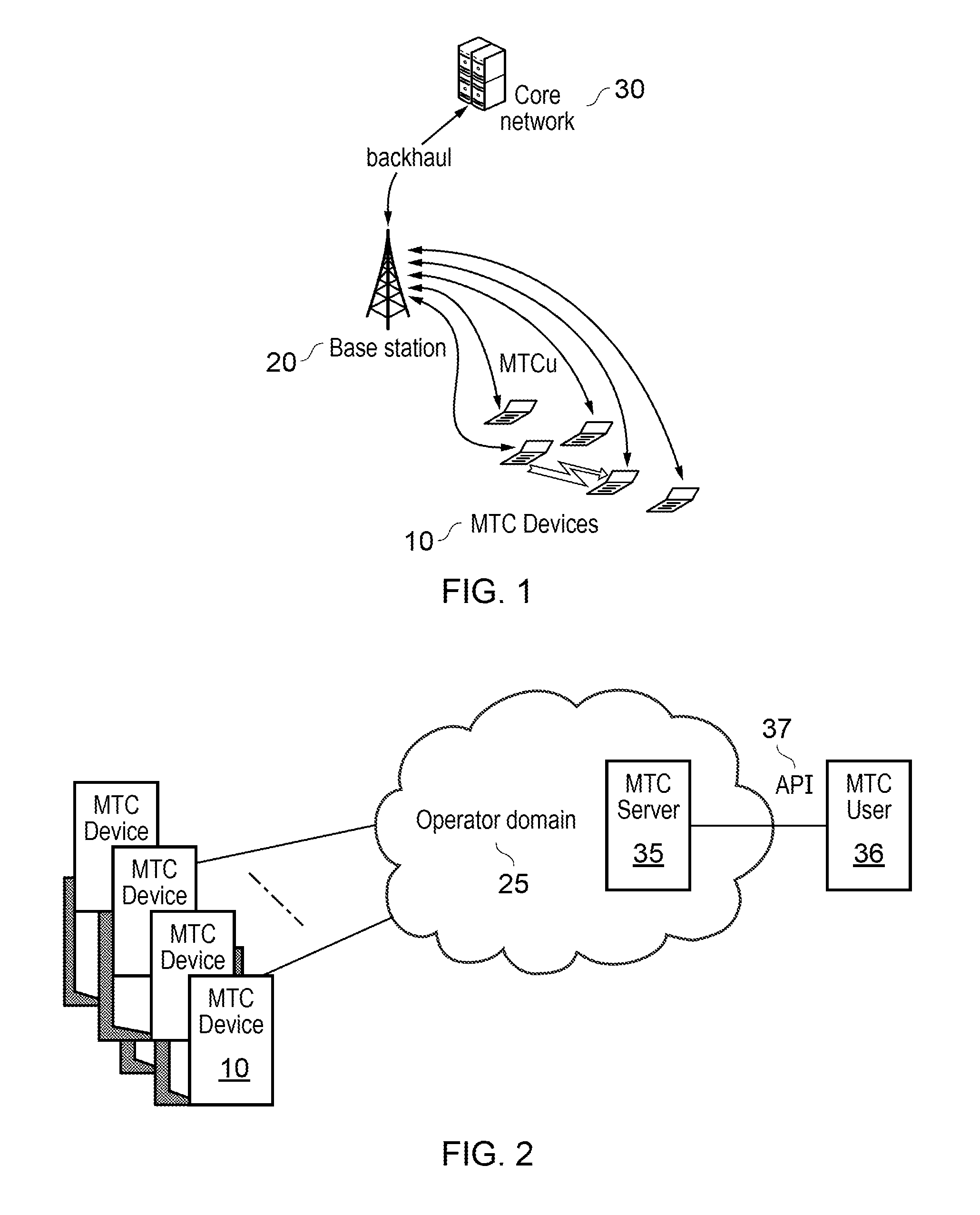
[0062]In the following description, the term base station is used to denote the interface point between the radio interface used to connect a wireless device (e.g., MTC device) and the core network. This may or may not be a cellular base station as for example found in cellular standards such as GSM / UMTS / LTE.

[0063]FIG. 1 schematically shows interference between a plurality of MTC devices 10 operating from the same base station 20 using the same or different frequency bands. The base station 20 communicates with a core network 30 via a backhaul (usually a wired connection).

[0064]In FIG. 1, MTCu denotes the radio interface that is used to send and receive information from the MTC devices 10. The interface labelled MTCu in the Figure represents any radio communication method that can be use...


PUM


Abstract

A scheme to reduce the problem of radio interference between wireless devices such as MTC devices in a multi-RAT scenario. Wireless devices are configured (S10) for interference reporting in accordance with their capabilities. Information is collected, not only on interference measurements reported by the wireless devices, but also on device signatures (S12) and transmission patterns (S14) for the purpose of attributing interference, suffered by a reporting device, to one or more offending devices (S16). One or more mitigation techniques is then applied to the offending device and / or the reporting device (S20-S24). The scheme provides an additional stability mechanism for existing interference mitigation and co-existence schemes by using device management and avoiding potential conflicts across diverse systems. Under the assumption that geographically co-located devices are all using a common service platform, the centralized algorithm permits more efficient solutions than existing interference mitigation solutions.

Description

FIELD OF THE INVENTION[0001]This invention generally relates to wireless communication networks and in particular, though not exclusively, to Machine Type Communication (MTC) in such networks, where MTC is a form of data communication which involves one or more entities that do not necessarily need human interaction.[0002]The two main standards groups involved in MTC are the 3rd Generation Partnership Project (3GPP) and the European Telecommunications Standardization Institute (ETSI). The term MTC is essentially synonymous with Machine-to-Machine Communication (M2M) as used by ETSI. ETSI defines an M2M device as one capable of replying to a request for data contained within the device, or capable of transmitting data contained within it autonomously.BACKGROUND OF THE INVENTION[0003]MTC is different from current communication models as it involves new or different market scenarios. Potentially it involves very large number of communicating entities (MTC devices) with little traffic p...

Claims


Application Information

Patent Timeline
Patent Type & Authority Patents(United States)
IPC IPC(8): H04B15/00H04J11/00H04W4/70H04W16/14H04W72/08H04W72/12
CPCH04W16/14H04W4/005H04J11/0023H04W72/1215H04W72/082H04W4/70H04W72/541
Inventor BUCKNELL, PAULCHEBBO, HINDOGUNBEKUN, JUMOKETESANOVIC, MILOS
Owner FUJITSU LTD
Learn More