
Doorbell communication systems and methods

a communication system and doorbell technology, applied in the field of doorbells, can solve the problems of false detection of the presence of visitors, inability of doorbells to detect visitors, and inability to detect visitors, so as to reduce the first probability, improve the accuracy of the doorbell system, and reduce the first sensitivity of the visitor detection system

Active Publication Date: 2015-04-21
SKYBELL TECH IP LLC
View PDF84 Cites 288 Cited by
  • Summary
  • Abstract
  • Description
  • Claims
  • Application Information

AI Technical Summary

Benefits of technology

[0018]Embodiments can grow more confident of indicators if they are followed by a visitor pressing the doorbell button. In some embodiments, all areas of the field of view are configured to trigger an alert regarding the visitor until indications associated with certain areas are not followed by visitors pressing the button. Then, the system can ignore indications in those areas (to reduce the number of false positives).
[0068]The portion of the field of view can be consistent between the calibration image and subsequent images to help the system accurately analyze the images. In some methods, the first image, the second image, and the third image consist of at least a portion of the field of view, wherein the method further comprises analyzing the portion of the field of view.

Problems solved by technology

For example, a homeowner located remotely from her home might not be able to hear the alerting sound, and thus, might not be aware that someone is ringing her doorbell.
Some doorbells, however, may falsely detect the presence of a visitor.
Some doorbells may fail to detect a visitor.
In many cases, infrared signatures suggestive of visitors are actually from visitors, but in some cases, infrared signatures suggestive of visitors may be misleading (and not actually be from visitors).
Thus, embodiments can grow more skeptical of indicators if they are not followed by, for example, a visitor pressing the doorbell button.
This exclusion often will not prevent all indications from causing an alert if the indications are detected in non-excluded zones.

Method used


Image

  • Doorbell communication systems and methods
  • Doorbell communication systems and methods
  • Doorbell communication systems and methods

Examples


Embodiment Construction

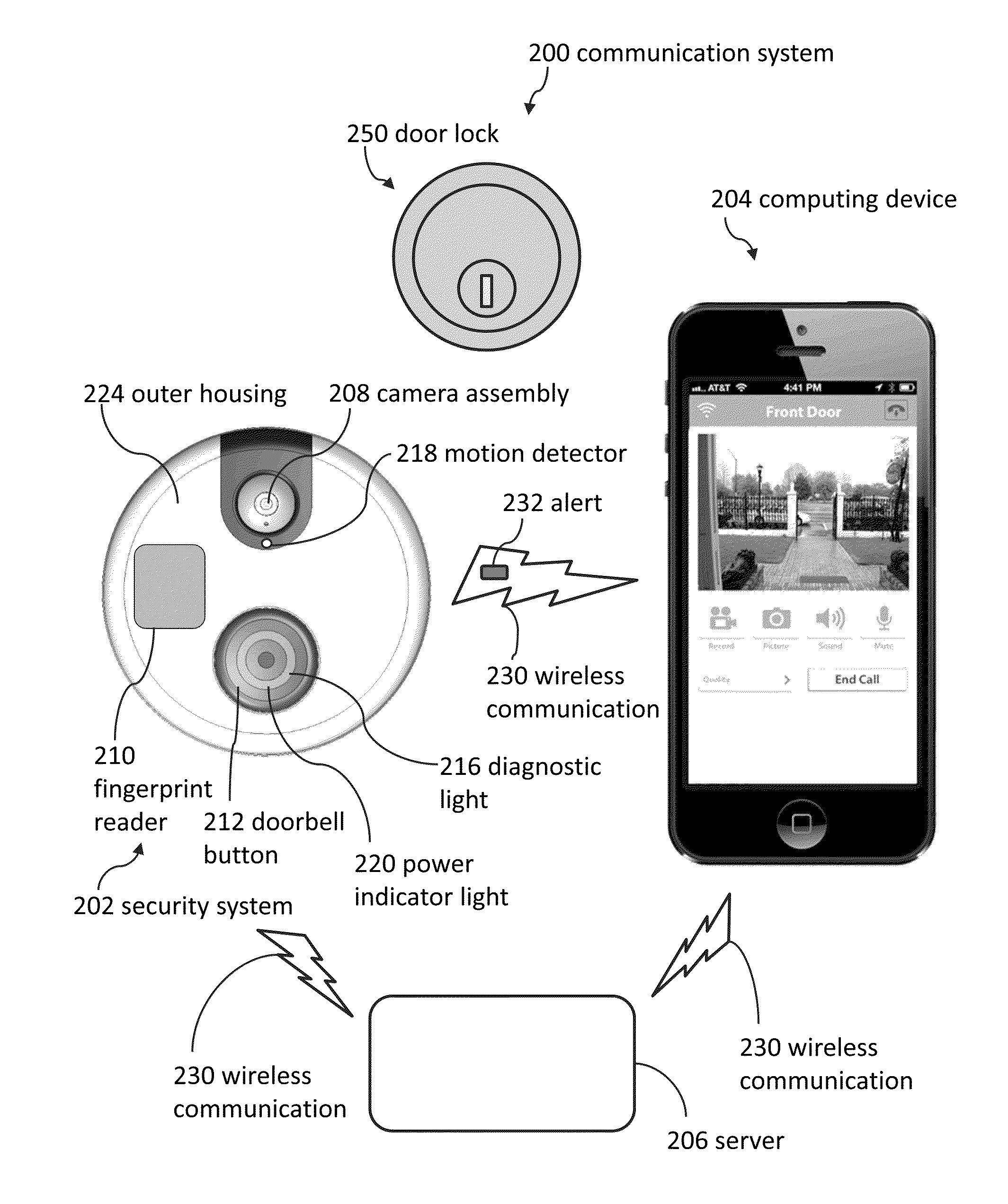
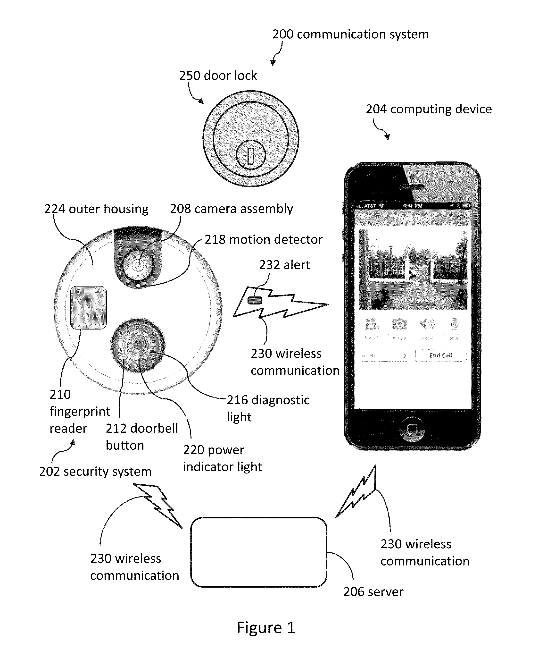
[0097]Although certain embodiments and examples are disclosed below, inventive subject matter extends beyond the specifically disclosed embodiments to other alternative embodiments and / or uses, and to modifications and equivalents thereof. Thus, the scope of the claims appended hereto is not limited by any of the particular embodiments described below. For example, in any method or process disclosed herein, the acts or operations of the method or process may be performed in any suitable sequence and are not necessarily limited to any particular disclosed sequence. Various operations may be described as multiple discrete operations in turn, in a manner that may be helpful in understanding certain embodiments; however, the order of description should not be construed to imply that these operations are order dependent. Additionally, the structures, systems, and / or devices described herein may be embodied as integrated components or as separate components.

[0098]For purposes of comparing...


PUM


Abstract

Doorbells can be used to detect visitors. Doorbells can have a field of view that includes a first portion and a second portion. Some embodiments include using a doorbell to detect a first object within the first portion of the field of view, and then determining if a doorbell button is pressed. If the doorbell button is not pressed, the doorbell may become less sensitive to objects detected in the first portion of the field of view. If the doorbell button is pressed, the doorbell may become more sensitive to objects detected in the first portion of the field of view. Multiple portions of the field of view may be independently adjusted based on doorbell button data.

Description

CROSS-REFERENCE TO RELATED APPLICATIONS[0001]This application claims the benefit of and is a continuation-in-part of U.S. Nonprovisional patent application Ser. No. 14 / 463,548; filed Aug. 19, 2014; and entitled DOORBELL COMMUNICATION SYSTEMS AND METHODS; which claims the benefit of U.S. Provisional Patent Application No. 62 / 035,646; filed Aug. 11, 2014; and entitled DOORBELL COMMUNICATION SYSTEMS AND METHODS. The entire contents of patent application Ser. No. 14 / 463,548 and Patent Application No. 62 / 035,646 are incorporated by reference herein.[0002]This application claims the benefit of and is a continuation-in-part of U.S. Nonprovisional patent application Ser. No. 14 / 502,601; filed Sep. 30, 2014; and entitled DOORBELL COMMUNICATION SYSTEMS AND METHODS. The entire contents of patent application Ser. No. 14 / 502,601 are incorporated by reference herein.[0003]This application claims the benefit of and is a continuation-in-part of U.S. Nonprovisional patent application Ser. No. 14 / 492...

Claims


Application Information

Patent Timeline
Patent Type & Authority Patents(United States)
IPC IPC(8): H04N7/18H04N9/47G08B3/10
CPCH04N7/188G08B3/10H04N7/186H04M11/025H04N1/00214H04N1/00225H04N7/183H04N23/661H04N23/631G06V20/52H04N23/45H04N23/56G01J1/0214
Inventor SCALISI, JOSEPH FRANK
Owner SKYBELL TECH IP LLC
Learn More