Diverting pulley arrangement and elevator

a technology of diverting pulleys and pulleys, which is applied in the direction of elevators, hoisting equipment, transportation and packaging, etc., can solve the problems of not eliminating the support of diverting pulleys, and achieve the effect of reducing the dependence on the direction of rotation

Active Publication Date: 2015-04-21
KONE CORP
View PDF22 Cites 3 Cited by
  • Summary
  • Abstract
  • Description
  • Claims
  • Application Information

AI Technical Summary

Benefits of technology

[0003]The aim of the invention is to eliminate, among others, the aforementioned drawbacks of prior-art solutions. More particularly the aim of the invention is to produce a safe diverting pulley arrangement and elevator that are improved from the standpoint of maintenance. The aim of the invention is further to produce one or more of the following advantages, among others:
[0004]A solution is achieved with which it can be ensured that failure of the locking of the axle of the diverting pulley does not result in the axle moving out of its position.
[0005]A solution is achieved with which servicing procedures can be speeded up and made more efficient.

Problems solved by technology

Thus damaging of the locking element or rupture pin, et cetera, does not eliminate the support of the diverting pulley.

Method used


Image

  • Diverting pulley arrangement and elevator
  • Diverting pulley arrangement and elevator
  • Diverting pulley arrangement and elevator

Examples


Embodiment Construction

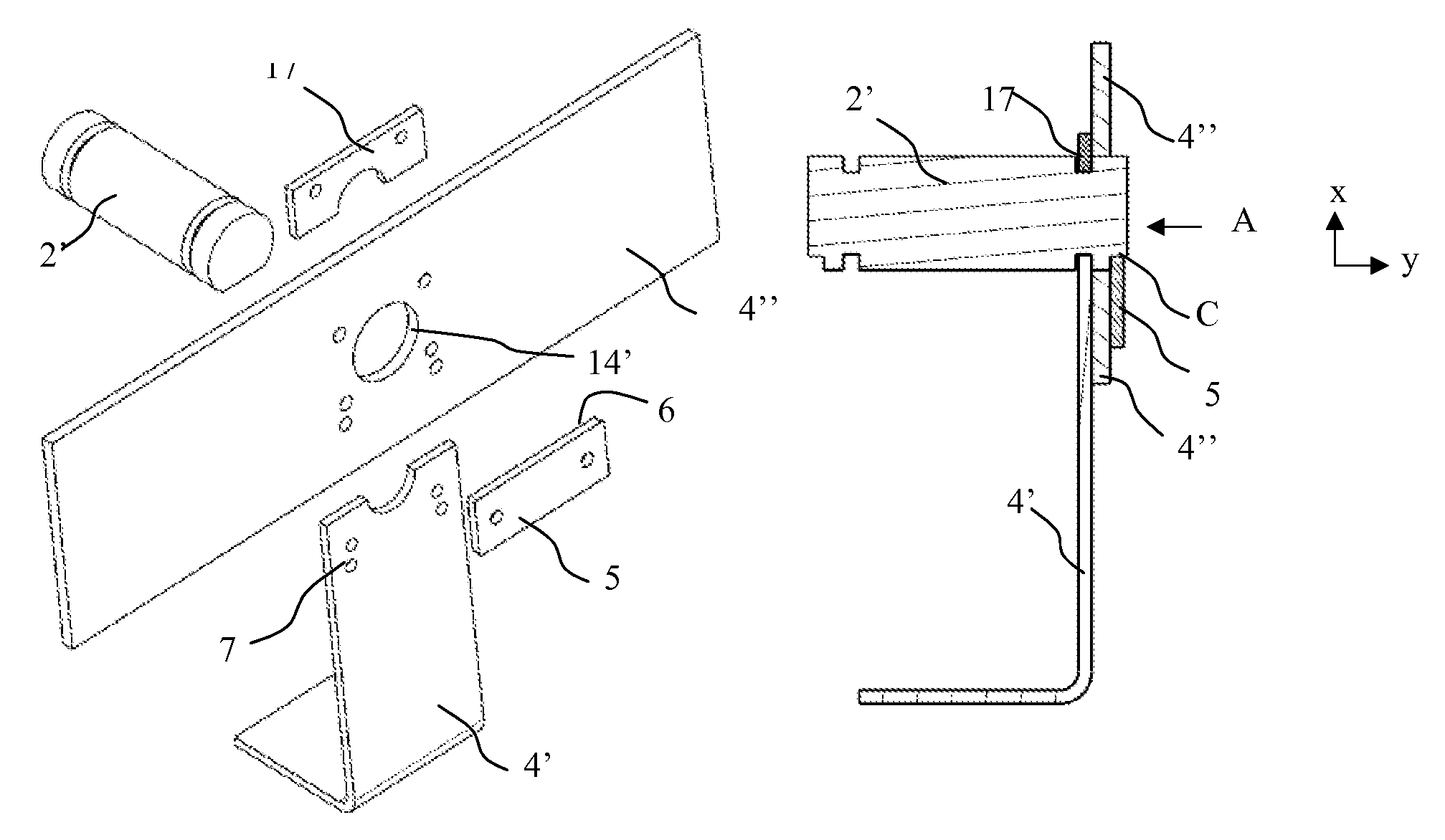
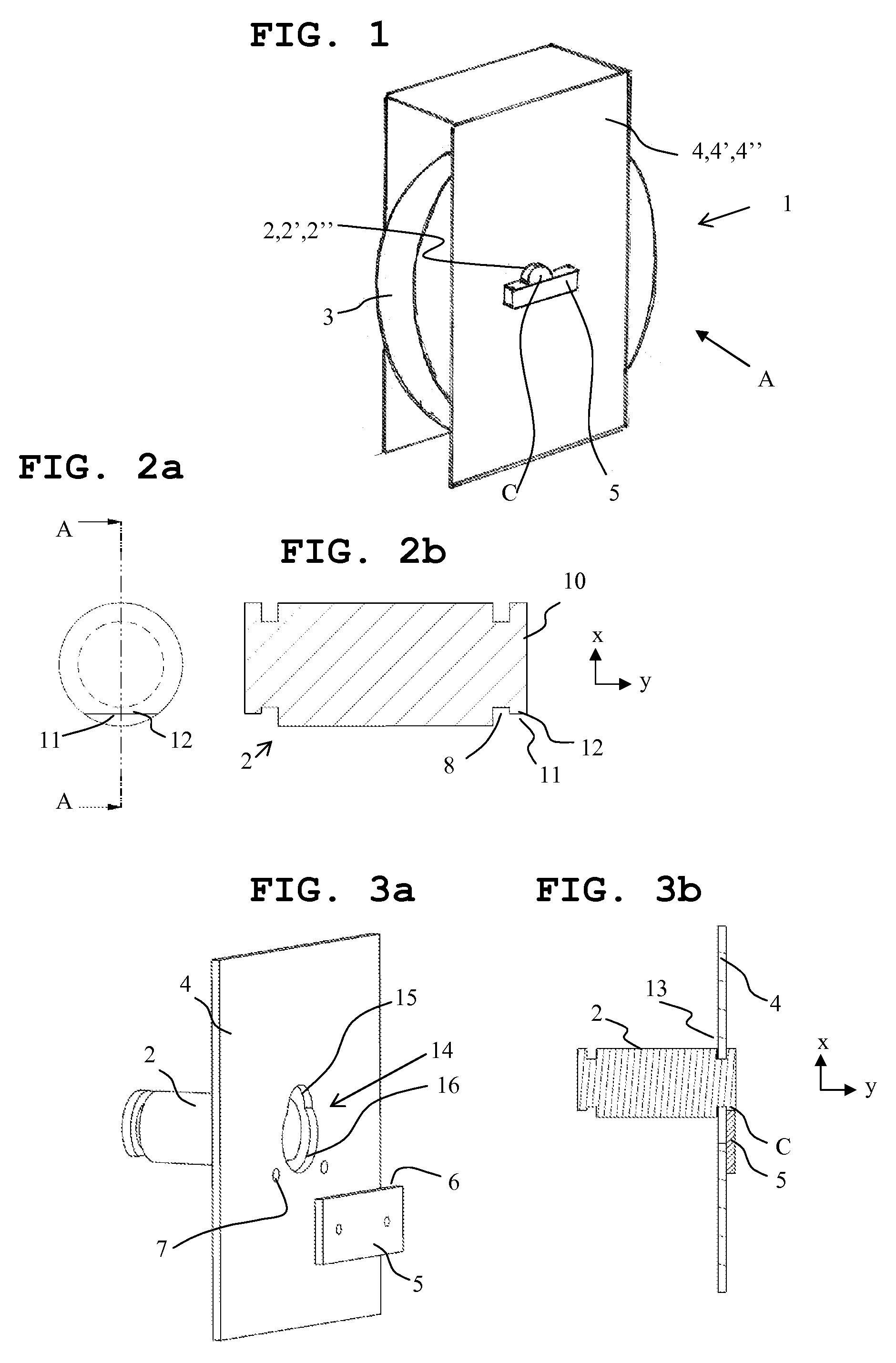
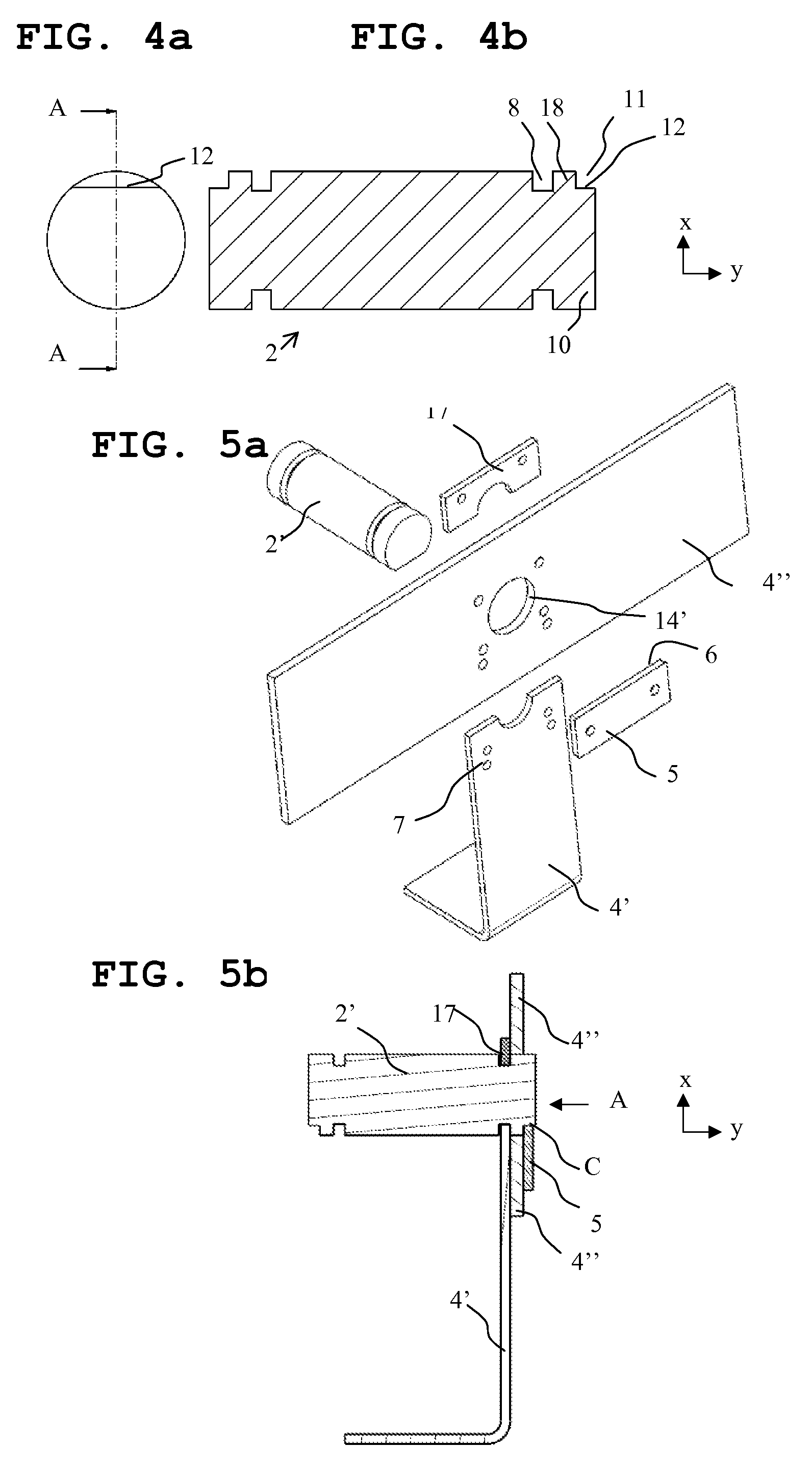
[0047]FIG. 1 presents in principle an assembly drawing of one diverting pulley arrangement 1 according to the invention, which comprises an axle 2,2′,2″, at least one diverting pulley 3 that rotates preferably around the axle while supported on the axle, a faceplate structure 4,4′,4″ on the side of the diverting pulley, which faceplate structure preferably comprises at least one faceplate, in relation to which and supported by which faceplate structure the diverting pulley 3 is arranged to rotate supported on the axle 2,2′,2″ on the first side of the faceplate structure. The axle 2,2′,2″ is locked so that it does not rotate in relation to the faceplate structure by the aid of a locking element 5, which locking element 5 is on the second side of the faceplate structure 4,4′,4″, which second side is on the opposite side to the first side and supported so that it does not move in relation to the faceplate structure 4,4′,4″. The locking element 5 is placed against the detent surface 6 o...


PUM


Abstract

Diverting pulley arrangement of an elevator, which includes an axle, at least one diverting pulley that rotates while supported on the axle, a faceplate structure, in relation to which and supported by which the diverting pulley is arranged to rotate on the first side of the faceplate structure, which axle is locked so that it does not rotate in relation to the faceplate structure by the aid of a locking element, which locking element is on the second side of the faceplate structure and supported so that it does not move in relation to the faceplate structure. The locking element is placed against the locking surface included in the axle so that the contact point of the locking element and the locking surface of the axle is at least partly visible.

Description

FIELD OF THE INVENTION[0001]The object of the invention is a diverting pulley arrangement preambleBACKGROUND OF THE INVENTION[0002]In prior-art diverting pulleys the axle of the diverting pulley is locked into position with a locking plate that extends into a groove made in the axle. The groove is milled into the axle from the transverse direction, in which case the groove comprises a detent surface as viewed in the transverse direction of the axle, against which the locking plate is placed to lock the axle in position so that it does not rotate and does not move in the axial direction. A problem in these prior-art solutions is that when the locking plate breaks and allows the axle to rotate, movability of the axle is also enabled in the axial direction. Another problem in these prior-art solutions is that since the groove is milled in the solutions at a distance from the end of the axle, the detent surface that is against the locking plate has remained hidden behind the end of the ...

Claims


Application Information

Patent Timeline
Patent Type & Authority Patents(United States)
IPC IPC(8): B66B15/02B66B7/00B66B11/08B66B11/00B66D3/04B66D3/26
CPCB66B15/02B66D3/04B66D3/26B66B11/008Y10T74/1987B66B7/06F16B21/16
Inventor SAARELAINEN, ANTTIVALJUS, PETTERIKALLIOMAKI, JAAKKONORJA, JUKKARAZVAN, ALBU
Owner KONE CORP
Why Eureka
Try Eureka