
Chip collection system for a key cutting machine

a collection system and key cutting machine technology, applied in the direction of milling equipment, metal-working machine components, manufacturing tools, etc., can solve the problem of messy area surrounding the key cutting machin

Inactive Publication Date: 2015-04-14
LODGE HAROLD D
View PDF13 Cites 11 Cited by
  • Summary
  • Abstract
  • Description
  • Claims
  • Application Information

AI Technical Summary

Benefits of technology

This patent is about a system for a key cutting machine that can collect and organize chips and shavings. The system includes a trough with two parallel drawer rails and support rails for holding a beam. There is also a rigid grid member that spans the top of the trough and a sealed drawer for inserting a key cutting machine. The technical effect of this system is to facilitate the efficient and organized collection and utilization of chips and shavings during key cutting operations.

Problems solved by technology

The cutting operation removes material from the blank key, transforming it into the form of chips or shavings, and often leaving the area surrounding the key cutting machine quite messy.

Method used


Image

  • Chip collection system for a key cutting machine
  • Chip collection system for a key cutting machine
  • Chip collection system for a key cutting machine

Examples


Embodiment Construction

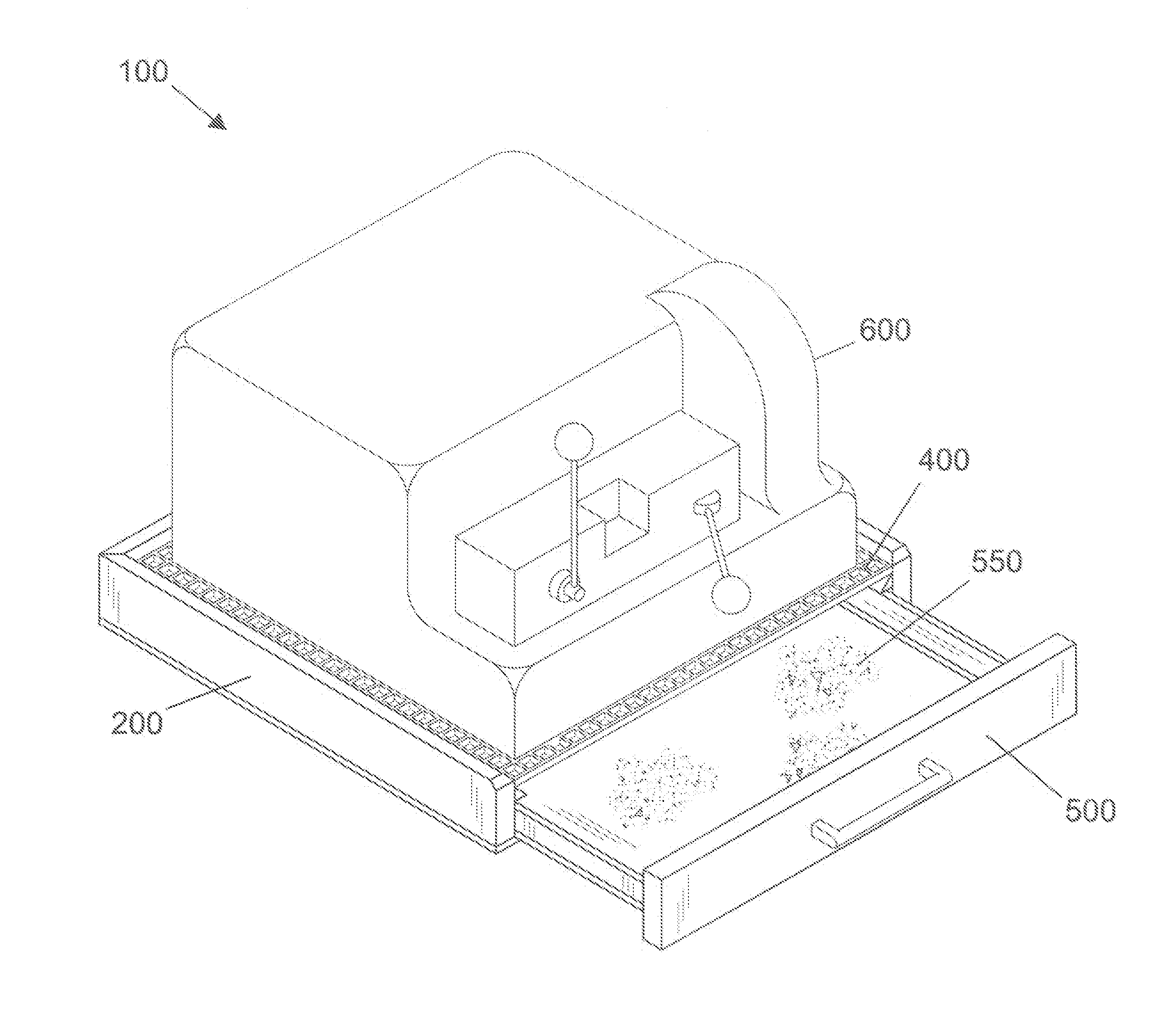
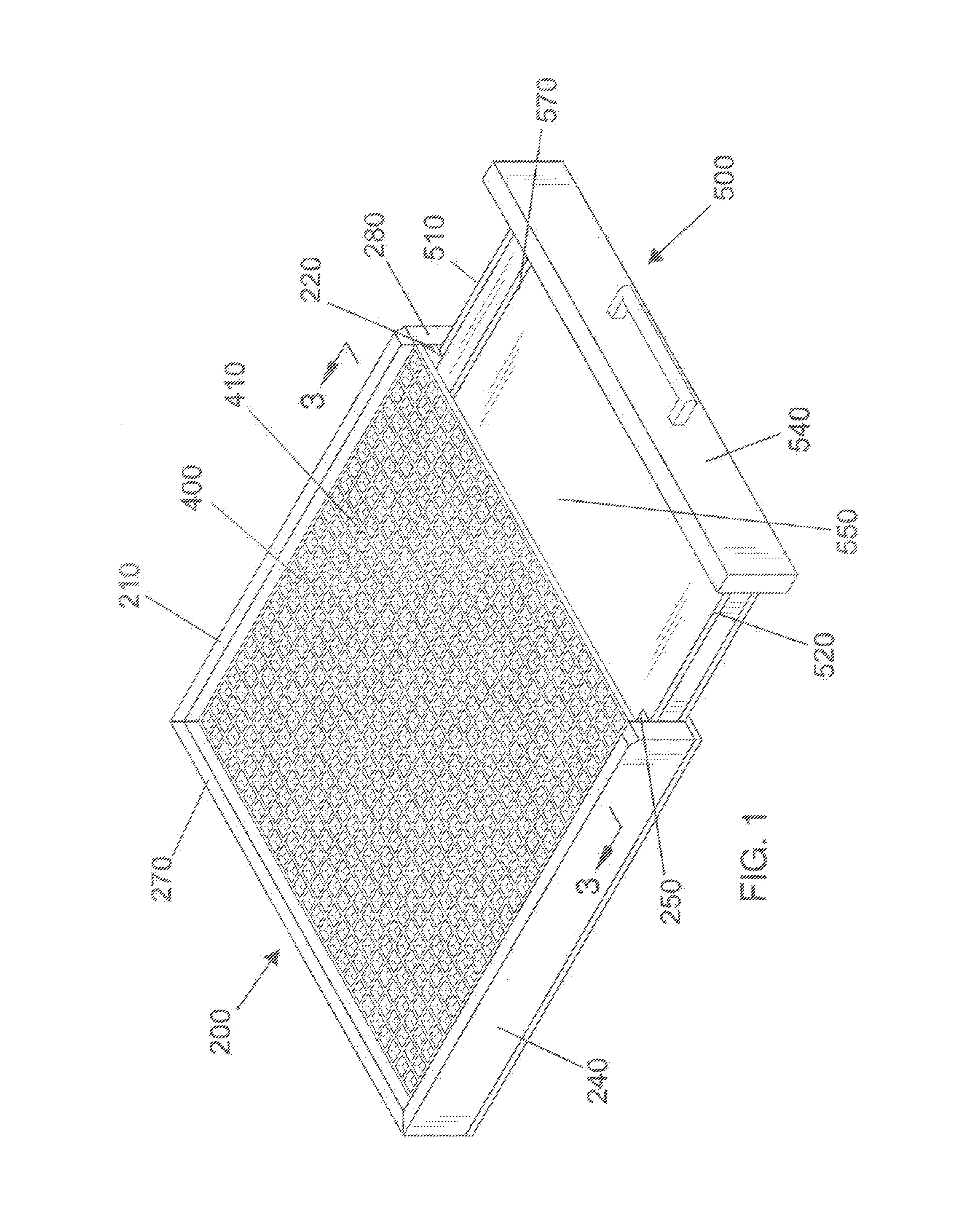
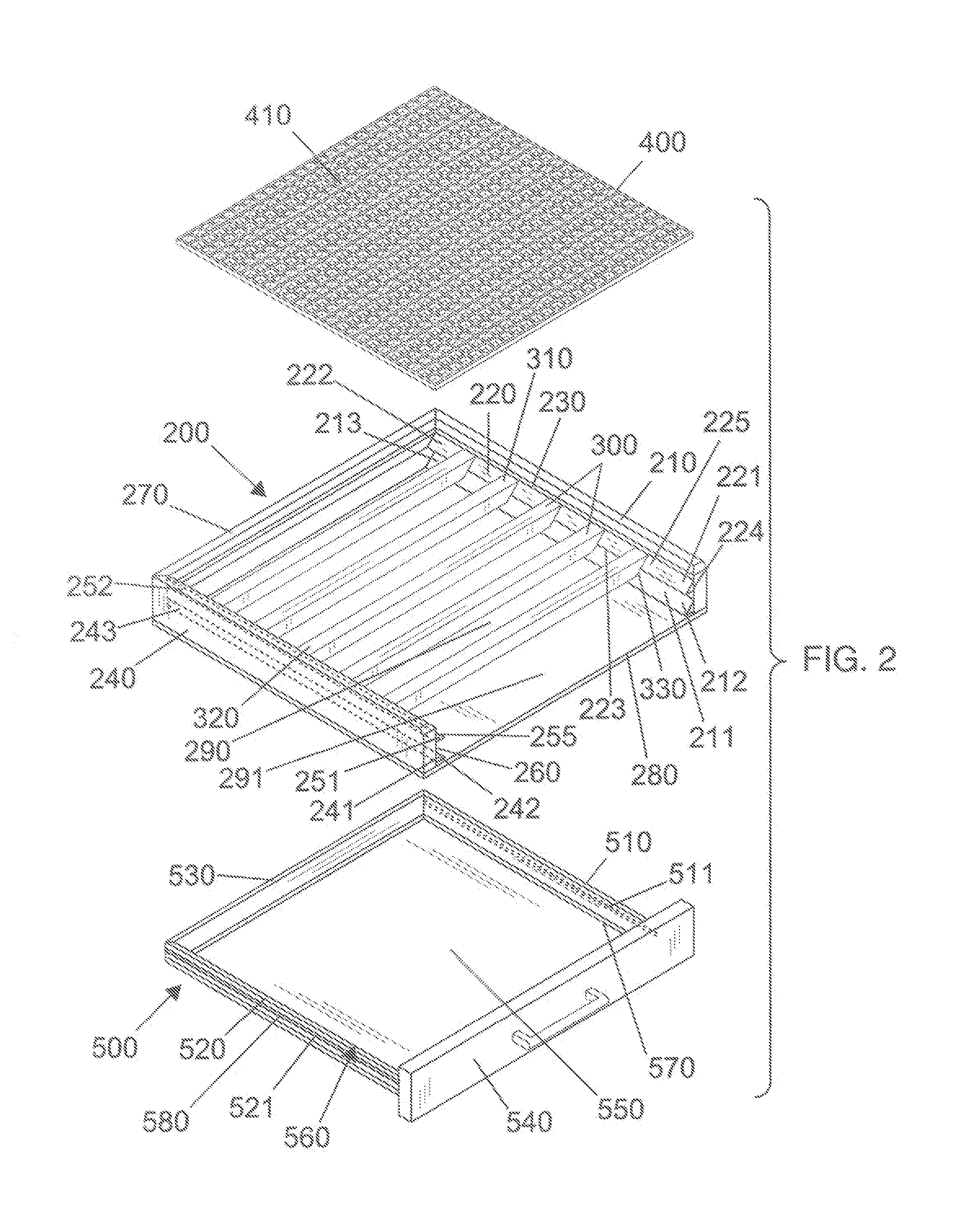
[0013]Following is a list of elements corresponding to a particular element referred to herein:[0014]100 Chip and shaving collection system[0015]200 Trough[0016]210 Trough first side[0017]211 First trough drawer rail[0018]212 First trough drawer rail first end[0019]213 First trough drawer rail second end[0020]220 First trough support rail[0021]221 First trough support rail first end[0022]222 First trough support rail second end[0023]223 First trough support rail bottom surface[0024]224 First trough support rail side surface[0025]225 First trough support rail mounting surface[0026]230 Trough first side inside surface.[0027]240 Trough second side[0028]241 Second trough drawer rail[0029]242 Second-trough drawer rail first end[0030]243 Second trough drawer rail second end.[0031]250 Second trough support rail[0032]251 Second trough support rail first end[0033]252 Second trough support rail second end[0034]253 Second trough support rail bottom surface[0035]254 Second trough support rail s...


PUM

PropertyMeasurementUnit
Fractionaaaaaaaaaa
Shapeaaaaaaaaaa

Abstract

A chip and shaving collection system for a key cutting machine has a trough with a linear first trough drawer rail located on a trough first side and a linear second trough drawer rail located on a trough second side. The trough further has a linear first trough support rail having a general shape of a triangular prism located on a trough first side and a linear second trough support rail having a general shape of a triangular prism located on a trough second side. The system has a plurality of linear support beams located on the support rails. The system has a rigid planar grid member spanning the trough top located on the linear support beams. The system has a drawer that is fluidly sealed located in the trough. The system has a key cutting machine located on the grid member.

Description

BACKGROUND OF THE INVENTION[0001]Key cutting is a primary method used for the duplication of keys. In this method, a flat key to be duplicated is fitted into a vise in a key duplication machine. A blank key is then inserted into a parallel vise. For operation, the original key is then moved along a guider simultaneously as the blank is moved against a cutting wheel. This operation duplicates the pattern into the formerly blank key. Once the cutting is complete, the new key is then deburred. The cutting operation removes material from the blank key, transforming it into the form of chips or shavings, and often leaving the area surrounding the key cutting machine quite messy. The present invention features a chip and shaving collection system for a key cutting machine to more effectively manage workspace cleanliness.SUMMARY[0002]The present invention features a chip and shaving collection system for a key cutting machine. In some embodiments, the system comprises a trough. In some emb...

Claims


Application Information

Patent Timeline
IPC IPC(8): B23C3/35B23Q11/00
CPCB23Q11/0067B23C3/35B23Q11/0053Y10T409/300952Y10T409/304088Y02P70/10
Inventor LODGE, HAROLD D.
Owner LODGE HAROLD D
Learn More