
Clasp for a watch bracelet

a technology for clasps and watches, applied in bracelets, wristwatch straps, apparel, etc., can solve the problems of permanent inability to disassemble clasps, inability to disassemble fine adjustment end links once, etc., and achieve the effect of limiting frictional forces and facilitating the movement of end links

Active Publication Date: 2015-04-14
OMEGA SA
View PDF14 Cites 34 Cited by
  • Summary
  • Abstract
  • Description
  • Claims
  • Application Information

AI Technical Summary

Benefits of technology

The simplified mechanical construction ensures reliable operation and easy maintenance of the fine adjustment mechanism, reducing frictional forces and eliminating the need for concealed screws, thus enhancing user experience and longevity of the clasp.

Problems solved by technology

Since this groove is limited at each end by a stop member which marks the bottom of the groove, it is quite impossible to disassemble the fine adjustment end link once the first screw has been screwed in.
In that case however, the clasp is permanently impossible to disassemble.

Method used


Image

  • Clasp for a watch bracelet
  • Clasp for a watch bracelet
  • Clasp for a watch bracelet

Examples


Embodiment Construction

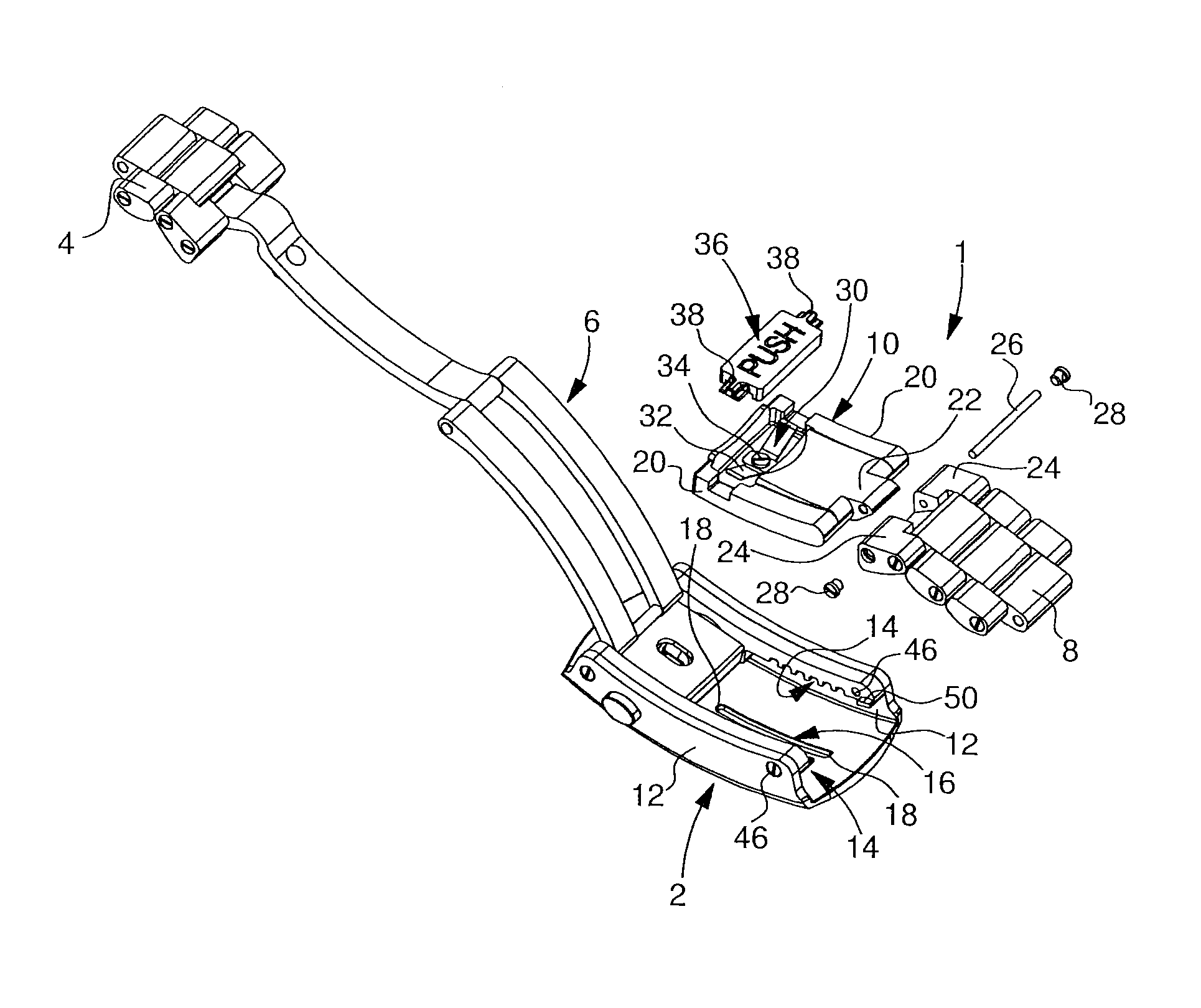
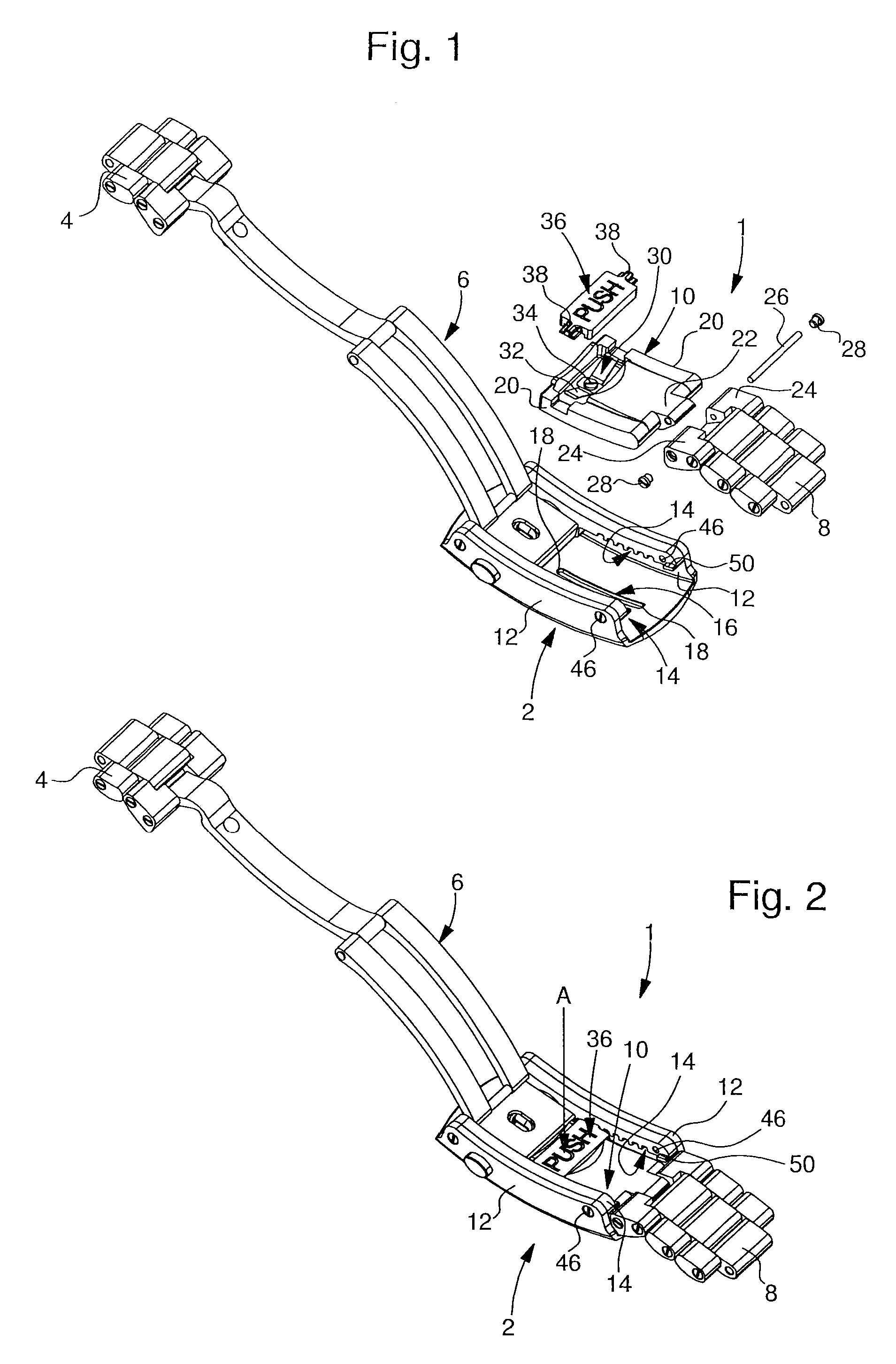
[0019]The present invention proceeds from the general inventive idea which consists in providing the sliding end link of a bracelet length fine adjustment system with an arresting means which is invisible to the user. Consequently, it is not necessary to take precautions to conceal the arresting means, which substantially simplifies the design of the clasp. Moreover, the end link slides on the bottom of the clasp cover on at least one skid, which reduces the surface contact between the end link and the cover. Frictional forces are thus reduced, so that it is easier to move the end link.

[0020]FIG. 1 is a perspective view of the clasp of the invention in an unassembled state, while FIG. 2 is a perspective view of the same clasp in the assembled state. Designated as a whole by the general reference numeral 1, the clasp according to the invention includes a cover 2, connected on a first side to a first bracelet strand 4, only two links of which can be seen in the drawing. An unfolding c...


PUM


Abstract

Clasp comprising a cover connected to a first bracelet strand and to a second bracelet strand, a connecting means being inserted between the second bracelet strand and the cover of the clasp, the connecting means comprising an end link sliding between a first position in which it is engaged in the cover of the clasp, and a second position in which it is outside the cover of the clasp, the end link comprising a push-button which causes a toothed element to change from a first position, in which the toothed element is in mesh with a rack toothing, to a second position, in which the toothed element is released, the end link being provided with an arresting means preventing the removal of the end link from the cover of the clasp, the arresting means comprising at least one lug, which projects into a groove arranged in the bottom of the cover and which defines two end stop members.

Description

[0001]This application claims priority from European Patent Application No. 13155028.7 filed 13.02.2013, the entire disclosure of which is incorporated herein by reference.FIELD OF THE INVENTION[0002]The present invention concerns a clasp for a watch bracelet or strap. More specifically, the present invention concerns a watch bracelet clasp comprising a means of finely adjusting the bracelet length.BACKGROUND OF THE INVENTION[0003]Clasps comprising means of fine adjustment of a watch bracelet length are already known in the state of the art. A clasp with fine adjustment of a bracelet length means a clasp which make it possible to adjust the bracelet length over a short travel for the best possible fit to optimise the comfort of the person wearing the watch. These clasps usually include an end link via which one of the bracelet strands is connected to the clasp cover. The end link is able to slide in a longitudinal direction of the clasp between a first “in” position in which it is h...

Claims


Application Information

Patent Timeline
Patent Type & Authority Patents(United States)
IPC IPC(8): A44C5/24
CPCA44C5/24A44C5/246Y10T24/2155
Inventor CATANESE, ROCCO
Owner OMEGA SA
Learn More