
Method of compensating for repeatable runout error

a repeatable runout and error technology, applied in the direction of maintaining head carrier alignment, recording signal processing, instruments, etc., can solve the problems of non-synchronous rro, head deviating from the desired circular path, and reducing the latency of non-synchronous rro, so as to reduce the latency and small data cache

Active Publication Date: 2015-04-07
WESTERN DIGITAL TECH INC
View PDF14 Cites 4 Cited by
  • Summary
  • Abstract
  • Description
  • Claims
  • Application Information

AI Technical Summary

Benefits of technology

The patent describes a method of writing data on a shingled magnetic recording (SMR) system, which allows for predictable and deterministic data writes. The method preloads data into a cache to reduce latency, and uses RRO data to control the write operations. The sequential nature of the SMR write operations also allows for smooth decompression of data when needed for specific tracks. The technical effects of this method include improved data write speed and efficiency, reduced latency, and improved data storage capacity.

Problems solved by technology

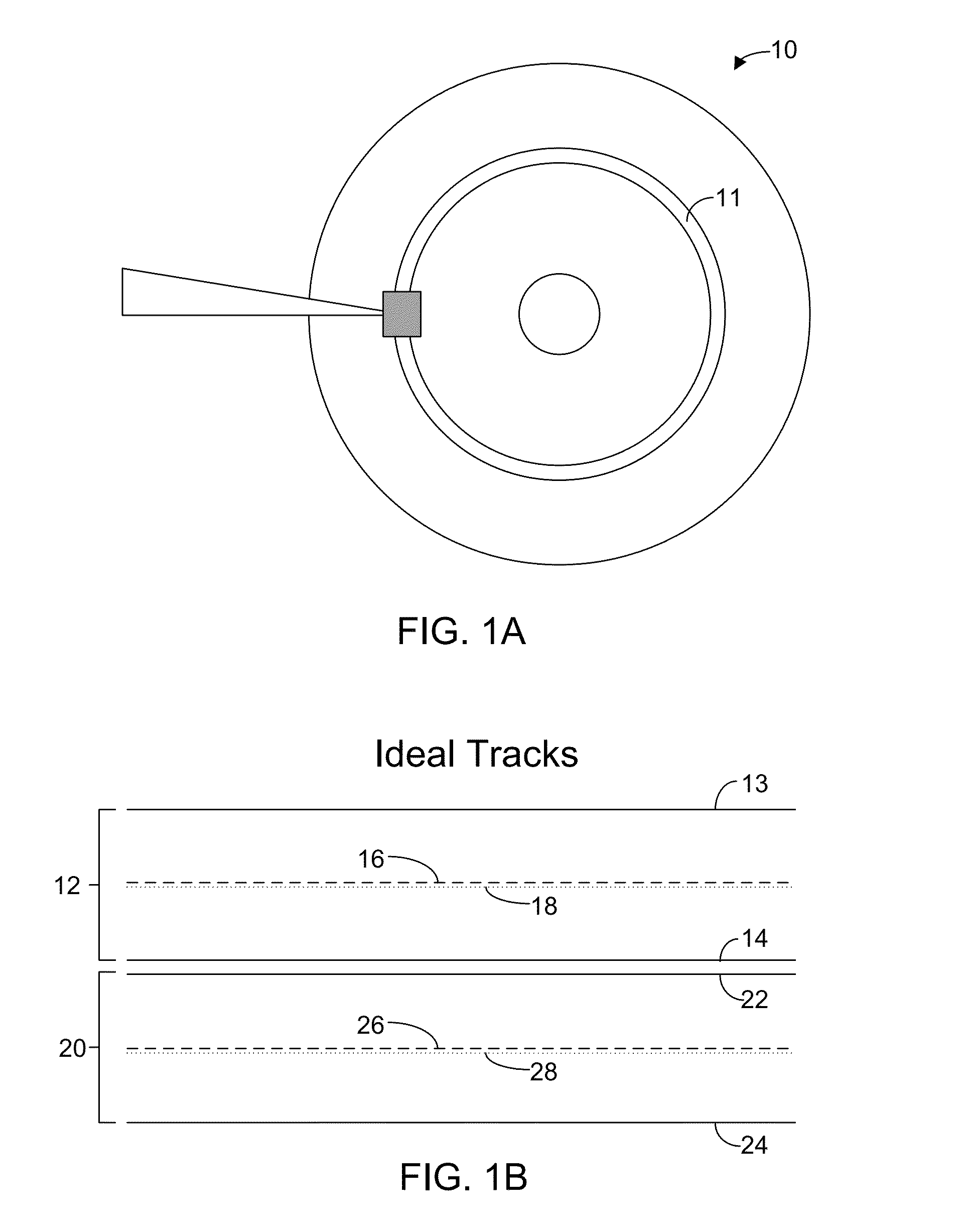
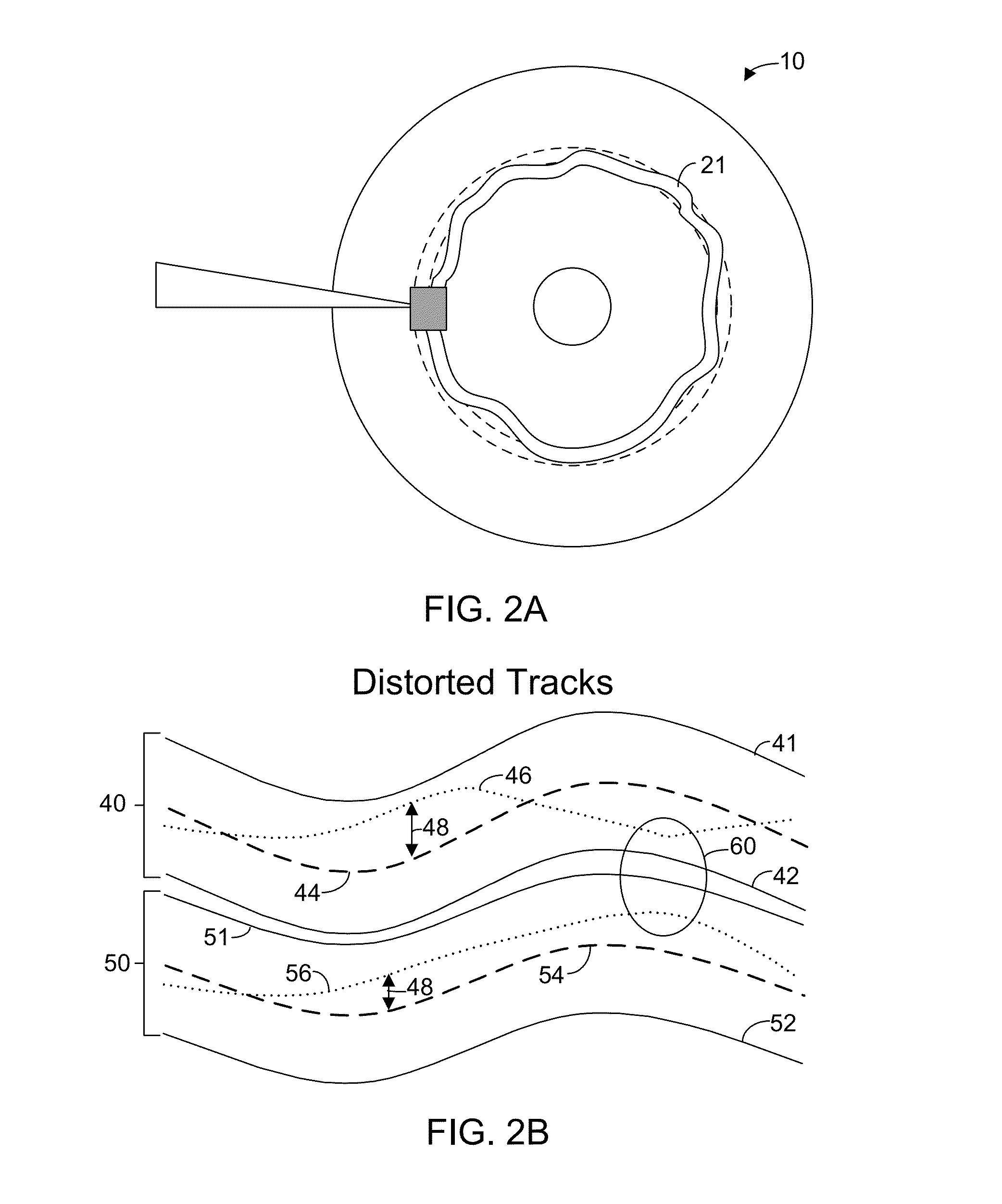
In reality, however, as a head attempts to follow a track it will not follow a perfect circular path.
Instead, the head will deviate from the desired circular path due to a variety of factors including disk irregularity, disk eccentricity, and / or misalignments of the spindle axis assembly.
Non-synchronous RRO is more problematic because it is unpredictable and varies from track to track.
Determining the offset values for each sector and writing the RRO data to the RRO field portion of the individual sector servo patterns is a very time consuming process.
Further, the RRO data is also spread out, so there is no efficient way to compress all of the RRO data to save on disk space.

Method used


Image

  • Method of compensating for repeatable runout error
  • Method of compensating for repeatable runout error
  • Method of compensating for repeatable runout error

Examples


Embodiment Construction

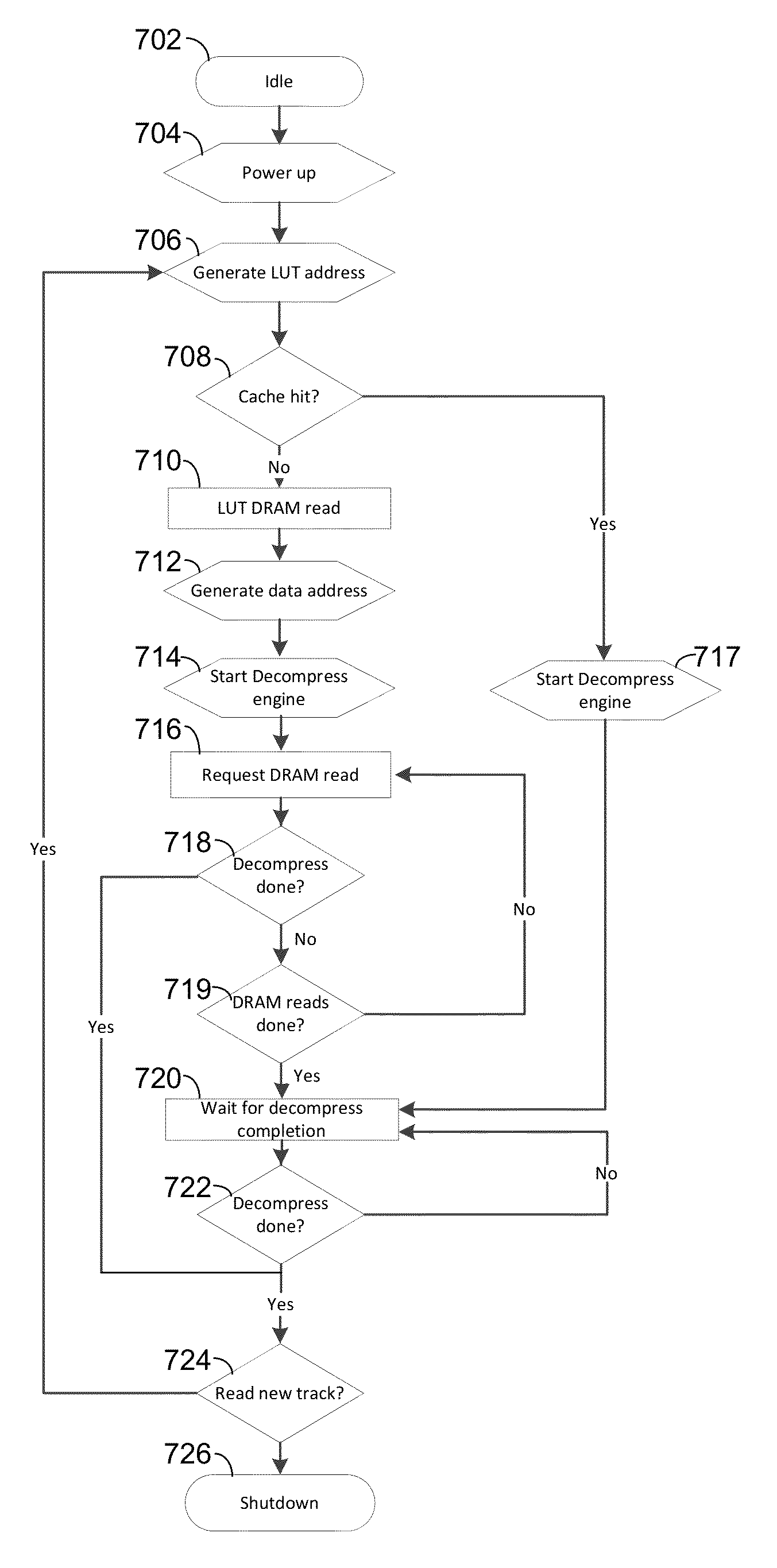
[0021]In preferred embodiments of the present invention, instead of storing RRO data in the servo patterns for each HDD track or sector, RRO data is instead stored in consolidated form within the reserved area of the disk. RRO data is preferably stored in reserved area of hard disk drive in compressed form. The compressed RRO data is subsequently read into DRAM in compressed form and then decompressed for use. Predictive techniques determine what compressed RRO-data is needed for upcoming read / write operations.

[0022]In some preferred embodiments, shingled magnetic recording (SMR) is utilized with data written in a shingled fashion so that data writes are predictable and deterministic. RRO data, which is used to control write operations, can be prefetched from the reserved area (RA) to dynamic random access memory (DRAM) so that it will be ready when needed. The sequential nature of SMR write operations means that a relatively small data cache can be used. When RRO-data is needed to ...


PUM

PropertyMeasurementUnit
diameteraaaaaaaaaa
areaaaaaaaaaaa
time-aaaaaaaaaa

Abstract

A method of correcting repeatable run out (RRO) errors for a HDD in which RRO data is instead stored in consolidated form within the reserved area of the disk, instead of storing RRO data in the servo patterns for each HDD track or sector. RRO data is preferably stored in the reserved area of a hard disk drive in compressed form. The compressed RRO data is subsequently read into DRAM in compressed form and then decompressed for use. Predictive techniques determine what compressed RRO data is needed for upcoming read / write operations.

Description

TECHNICAL FIELD OF THE INVENTION[0001]This invention relates generally to the field of rotating, data-storage devices, and more particularly, to correcting repeatable run out errors in disk drives.BACKGROUND[0002]Rotating data-storage devices, commonly referred to as hard disk drives (HDD), read and write information along concentric tracks formed on disks. To navigate to a particular track on a disk, disk drives may use servo fields on the disk. These fields are utilized by a servo subsystem to position a head over a particular track. Servo writers write the servo fields onto the disk in tracks when the disk drive is manufactured and these fields are then accessed by the disk drive to determine position. Hereinafter, the path defined by the servo fields shall be referred to as the “servo track” to distinguish it from a data track. Ideally, a head following the center of a servo track moves along a perfectly circular path around the disk. In such an ideal case, the servo track and d...

Claims


Application Information

Patent Timeline
Patent Type & Authority Patents(United States)
IPC IPC(8): G11B5/596
CPCG11B5/59627G11B20/10009G11B20/10527
Inventor COKER, JONATHAN D.FURLONG, JEFFREY L.HALLSTANEK, DAVID J.
Owner WESTERN DIGITAL TECH INC
Learn More