
Method and apparatus for in-flight blade folding

a technology of rotor blades and folding methods, applied in the field of rotor blades for rotorcraft, can solve the problems of limited forward speed and rang

Active Publication Date: 2015-04-07
TEXTRON INNOVATIONS
View PDF11 Cites 60 Cited by
  • Summary
  • Abstract
  • Description
  • Claims
  • Application Information

AI Technical Summary

Benefits of technology

Enables the aircraft to fly faster and farther by relying on jet thrust in a folded mode, reducing drag and maintaining efficiency while folding, and allowing for quick conversion between modes.

Problems solved by technology

During airplane mode of the tiltrotor, forward speed and range is limited by certain fundamental limitations of the rotor systems.

Method used


Image

  • Method and apparatus for in-flight blade folding
  • Method and apparatus for in-flight blade folding
  • Method and apparatus for in-flight blade folding

Examples


Embodiment Construction

[0012]Illustrative embodiments of the method and apparatus of the present application are described below. In the interest of clarity, not all features of an actual implementation are described in this specification. It will of course be appreciated that in the development of any such actual embodiment, numerous implementation-specific decisions must be made to achieve the developer's specific goals, such as compliance with system-related and business-related constraints, which will vary from one implementation to another. Moreover, it will be appreciated that such a development effort might be complex and time-consuming but would nevertheless be a routine undertaking for those of ordinary skill in the art having the benefit of this disclosure.

[0013]In the specification, reference may be made to the spatial relationships between various components and to the spatial orientation of various aspects of components as the devices are depicted in the attached drawings. However, as will be...


PUM


Abstract

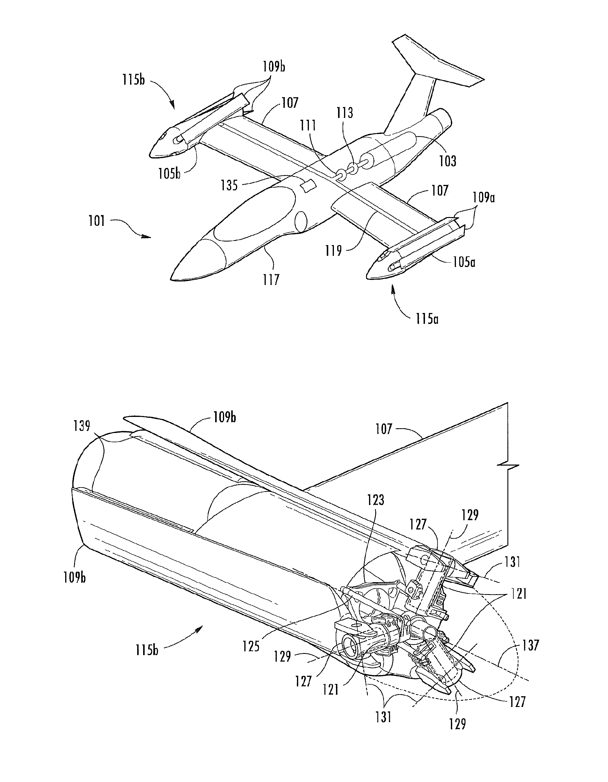
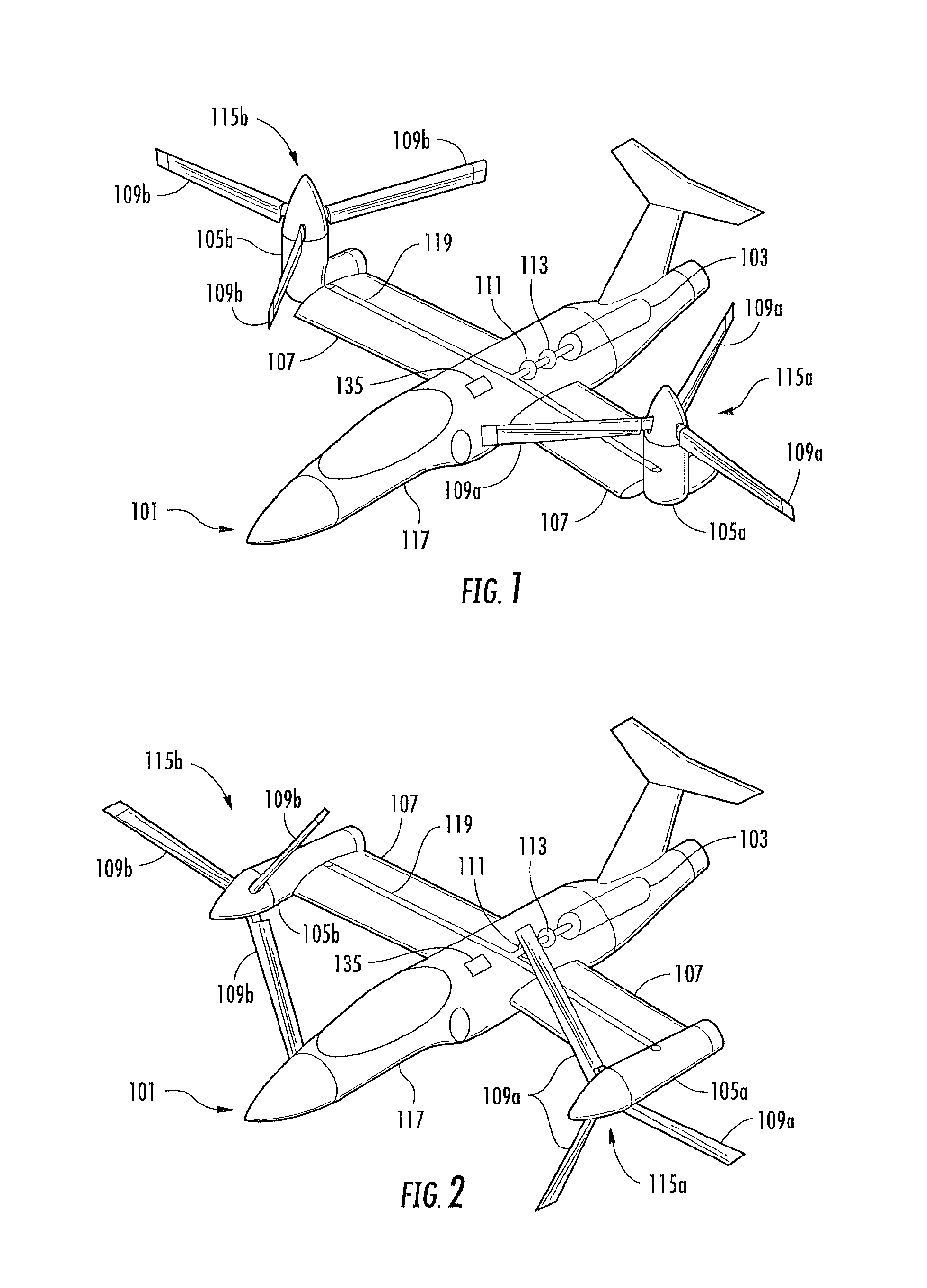
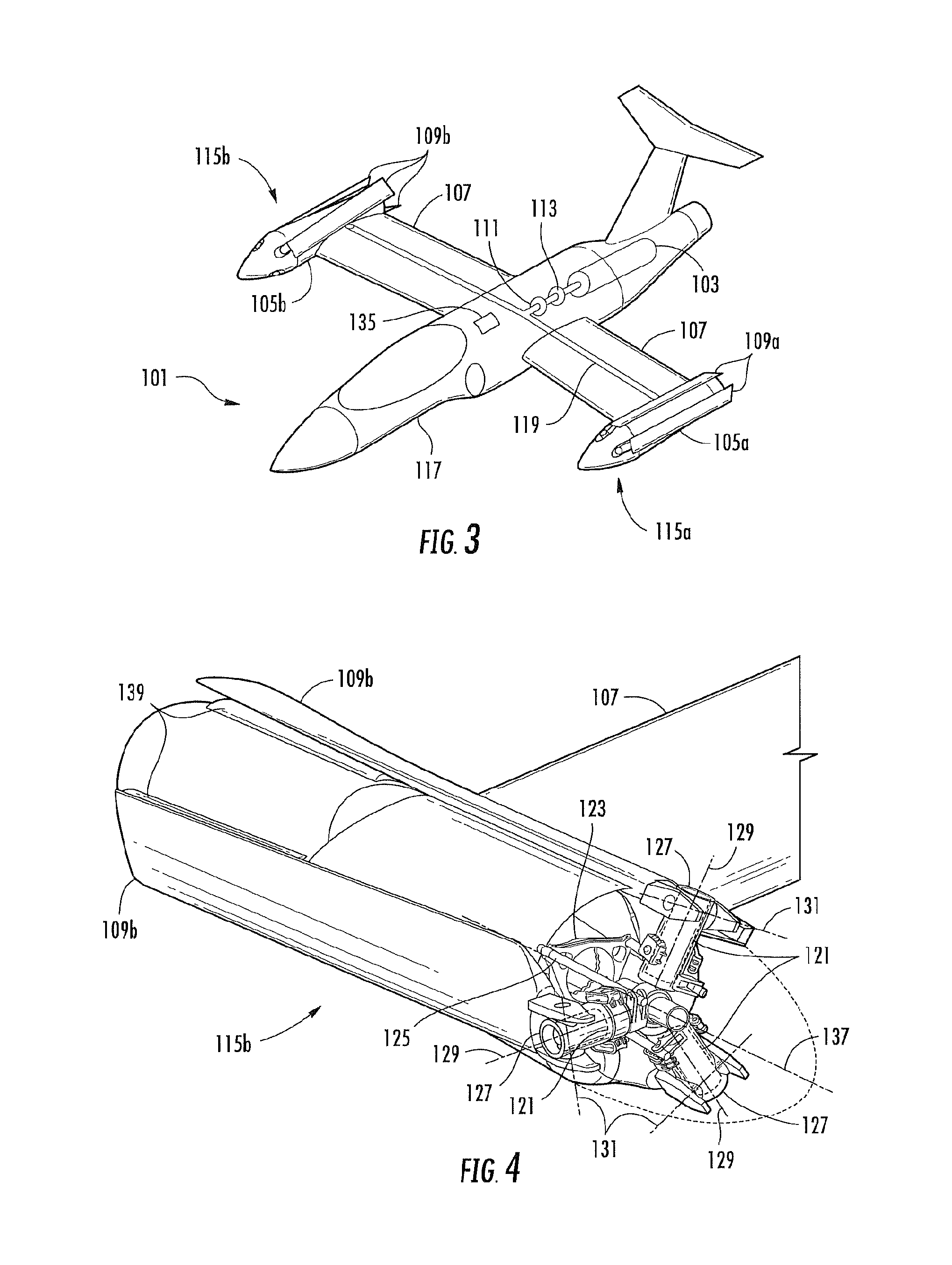
A foldable rotor system for a rotorcraft, the foldable rotor system comprising a rotor assembly operably associated with a driveshaft, the driveshaft being operable associated with an engine, the rotor assembly comprising a rotor blade connected to a grip pin. A swashplate is operable associated with the grip pin in order selectively change a pitch of the rotor blade. A blade fold actuator is operably associated with the grip pin such that the blade fold actuator is configured to fold and unfold the rotor blade about a blade fold axis. During an airplane mode, the rotorcraft can stop and fold the rotor blades so that the rotorcraft relies upon thrust from the engine for propulsion. The rotor blades are folded in a spiral fold path so that the rotor blades remain substantially edgewise, or feathered, during the folding process. The spiral fold path minimizes the aerodynamic drag experienced by the rotor blades while being folded during flight of the rotorcraft.

Description

TECHNICAL FIELD[0001]The present application relates in general to the field of rotor blades for rotorcraft; but more particularly, a method and apparatus for the folding of rotor blades during flight.DESCRIPTION OF THE PRIOR ART[0002]Tiltrotor aircraft are hybrids between traditional helicopters and traditional propeller driven aircraft. Typical tiltrotor aircraft have nacelles with rotor systems that are capable of rotating relative to the aircraft fuselage. Tiltrotor aircraft are capable of converting from a helicopter mode, in which the aircraft can take-off, hover, and land like a helicopter; to an airplane mode, in which the aircraft can fly forward like a fixed-wing airplane. During airplane mode of the tiltrotor, forward speed and range is limited by certain fundamental limitations of the rotor systems.BRIEF DESCRIPTION OF THE DRAWINGS[0003]The novel features believed characteristic of the method and apparatus of the present application are set forth in the appended claims. ...

Claims


Application Information

Patent Timeline
Patent Type & Authority Patents(United States)
IPC IPC(8): B64C27/28B64C27/30B64C29/00
CPCB64C29/0033B64C27/28B64C27/30
Inventor HOLLIMON, CHARLESSMITH, DUDLEY E.LUDOLPH, DAVID
Owner TEXTRON INNOVATIONS
Learn More