
Decoupling instrument shaft roll and end effector actuation in a surgical instrument

a technology of end effector and shaft roll, which is applied in the direction of surgical forceps, medical science, surgery, etc., can solve the problems of affecting the rotation of the drive shaft, the limited range of motion of the cable drive output coupler, and the detrimental effect of the limited range of motion

Active Publication Date: 2015-03-31
INTUITIVE SURGICAL OPERATIONS INC
View PDF27 Cites 1178 Cited by
  • Summary
  • Abstract
  • Description
  • Claims
  • Application Information

AI Technical Summary

Benefits of technology

[0014]Surgical assemblies and related methods are disclosed that provide for decoupling of instrument shaft roll and end effector actuation. In many embodiments, a differential is used to combine a motion associated with rotation of an instrument shaft with an input motion to generate an output motion to an actuation mechanism of an end effector supported by the distal end of the instrument shaft. The actuation mechanism articulates a portion of the end effector (e.g., a gripping jaw, a mechanism for the deployment of staples, a tissue cutting mechanism, etc.). The differential can be configured such that rotation of the instrument shaft results in substantially zero articulation of the end effector portion, thereby eliminating the possibility of any detrimental coupling between instrument shaft roll and end effector actuation.
[0022]Surgical assemblies and related methods are also disclosed that provide for the transmission of high levels of actuation torque to a rotary mechanism of an end effector supported by an independently rotatable main shaft without causing undesirable rotation of the main shaft. An input drive shaft is coupled with both the rotary mechanism and the main shaft via a transmission and a rotational coupling so that the main shaft is passively subjected to a counteracting torque opposite in direction to the actuation torque transmitted to the rotary mechanism so as to inhibit unintended rotation (e.g., back driving) of the main shaft. The disclosed assemblies and methods can be expanded to transmit high levels of actuation torque to two or more rotary mechanisms of an end effector while passively inhibiting unintended rotation of the main shaft. The disclosed assemblies and methods can be particularly advantageous when employed in minimally invasive robotic surgical assemblies and procedures.

Problems solved by technology

A cable driven output coupler typically has a limited range of motion.
Such a limited range of motion may, however, be detrimental where the output coupler is associated with a motion of the end effector that is impacted by another motion of the end effector.
For example, instrument shaft rotation may detrimentally couple with rotation of a drive shaft used to actuate an end effector mechanism (e.g., a clamping mechanism, a mechanism for the deployment of staples, a tissue cutting mechanism, etc.).
Although compensating motions of the output couplers associated with the rotation of the instrument shaft and rotation of the drive shaft can be made, such compensating motions reduce the portion of the limited range of motion of the output couplers that can be used for their primary purpose.
If the main shaft or the mechanism used to rotationally position the main shaft, is not sufficiently rigid, the main shaft may move unexpectedly in response to the reacted force or torque.

Method used


Image

  • Decoupling instrument shaft roll and end effector actuation in a surgical instrument
  • Decoupling instrument shaft roll and end effector actuation in a surgical instrument
  • Decoupling instrument shaft roll and end effector actuation in a surgical instrument

Examples


Embodiment Construction

[0076]In the following description, various embodiments of the present invention will be described. For purposes of explanation, specific configurations and details are set forth in order to provide a thorough understanding of the embodiments. However, it will also be apparent to one skilled in the art that the present invention may be practiced without the specific details. Furthermore, well-known features may be omitted or simplified in order not to obscure the embodiment being described.

[0077]Minimally Invasive Robotic Surgery

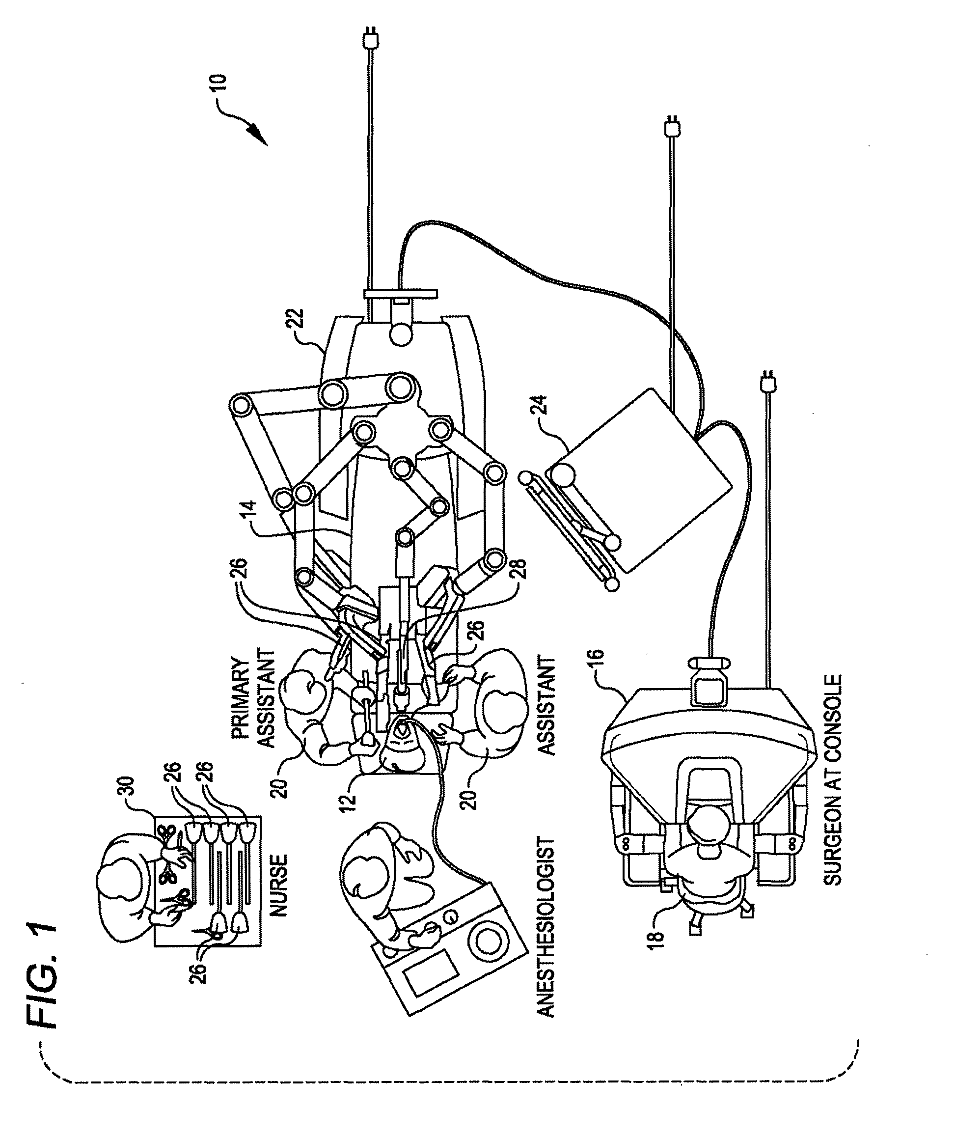
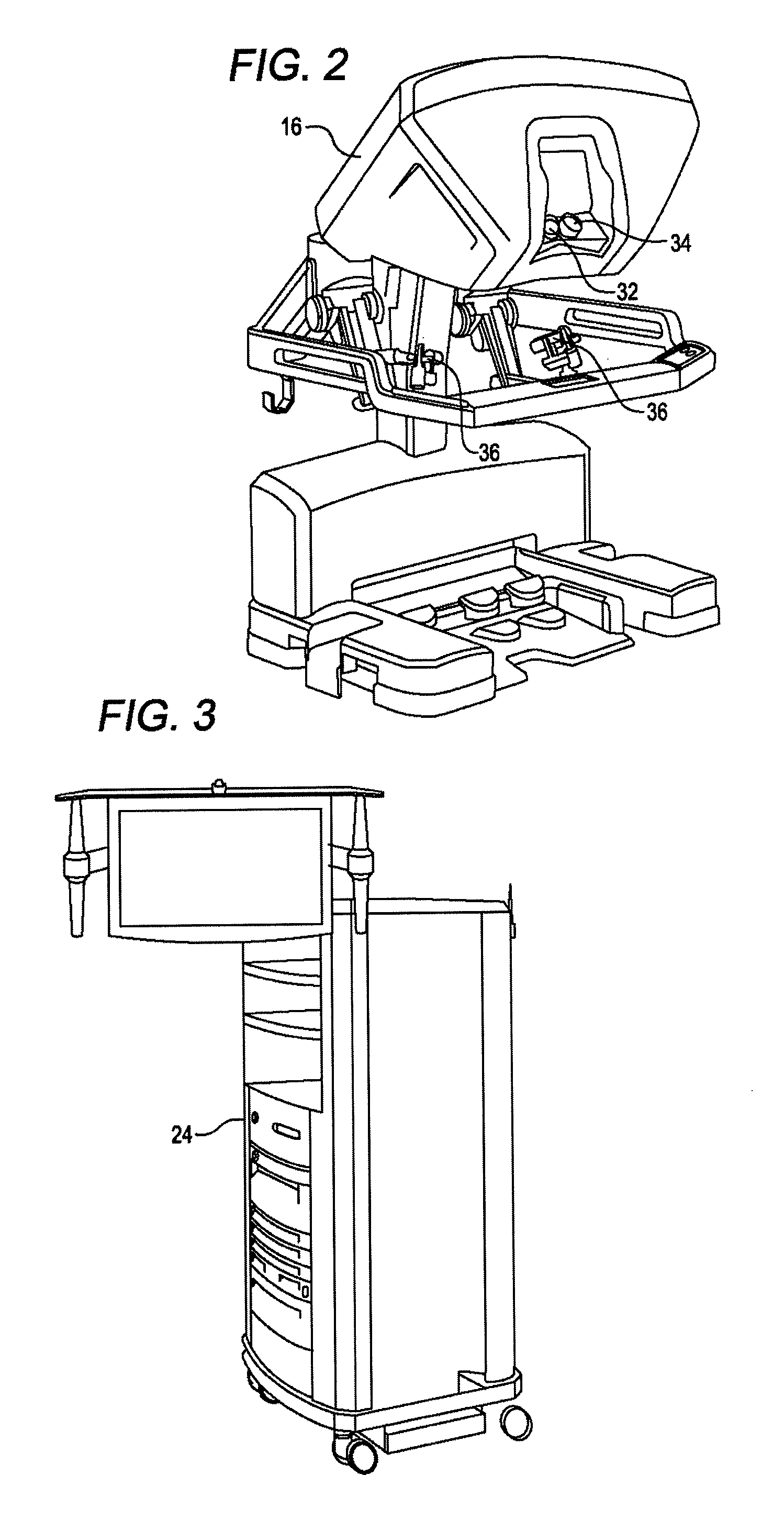
[0078]Referring now to the drawings, in which like reference numerals represent like parts throughout the several views, FIG. 1 is a plan view illustration of a Minimally Invasive Robotic Surgical (MIRS) system 10, typically used for performing a minimally invasive diagnostic or surgical procedure on a Patient 12 who is lying down on an Operating table 14. The system can include a Surgeon's Console 16 for use by a Surgeon 18 during the procedure. One or more...


PUM


Abstract

Surgical assemblies and related methods are disclosed that provide for decoupling of instrument shaft roll and end effector actuation. A surgical assembly includes a base, an instrument shaft rotationally mounted to the base, an end effector supported at a distal end of the instrument shaft and including an actuation mechanism driven by a rotational motion, a drive shaft rotationally coupled with the actuation mechanism and configured to provide the rotational motion to the actuation mechanism, and a differential rotationally coupled to the drive shaft and receiving a first input motion and a second input motion. The differential combines the first and second input motions to generate an output motion that rotates the drive shaft. The first input motion is rotationally coupleable to an actuation source. The second input motion is coupled to rotation of the instrument shaft relative to the base.

Description

CROSS-REFERENCES TO RELATED APPLICATIONS[0001]The present application claims the benefit of U.S. Provisional Application No. 61 / 413,885, entitled “METHOD FOR PASSIVELY DECOUPLING TORQUE APPLIED BY A REMOTE ACTUATOR INTO AN INDEPENDENTLY ROTATING MEMBER,” filed on Nov. 15, 2010; and U.S. Provisional Application No. 61 / 491,789, entitled “DECOUPLING INSTRUMENT SHAFT ROLL AND END EFFECTOR ACTUATION IN A SURGICAL INSTRUMENT,” filed on May 31, 2011; the full disclosures of which are incorporated herein by reference.BACKGROUND[0002]Minimally invasive surgical techniques are aimed at reducing the amount of extraneous tissue that is damaged during diagnostic or surgical procedures, thereby reducing patient recovery time, discomfort, and deleterious side effects. As a consequence, the average length of a hospital stay for standard surgery may be shortened significantly using minimally invasive surgical techniques. Also, patient recovery times, patient discomfort, surgical side effects, and ti...

Claims


Application Information

Patent Timeline
Patent Type & Authority Patents(United States)
IPC IPC(8): A61B17/28A61B17/29A61B17/00A61B19/00
CPCA61B19/22A61B19/2203A61B2017/2903A61B2017/293A61B2017/2936A61B2017/2943A61B2019/2242A61B2017/00477A61B2017/2938A61B34/71A61B34/30A61B2017/00398A61B2090/067A61B2034/2059A61B2034/301A61B34/32A61B2034/302A61B2034/303A61B34/37A61B2034/715A61B2017/2901A61B2017/2932A61B34/70A61B90/03A61B17/00234A61B17/29A61B2090/031A61B2017/2902A61B2017/00017A61B17/28A61B2017/2929A61B17/00A61B2017/00367
Inventor BRISSON, GABRIEL F.BURBANK, WILLIAM
Owner INTUITIVE SURGICAL OPERATIONS INC
Learn More