
Slide-out room system having wall-mounted drive mechanisms

a technology of drive mechanism and sliding room, which is applied in the direction of transportation and packaging, transportation items, transportation vehicles, etc., can solve the problems of difficult to address, damage the drive mechanism, and the wall of the sliding room may bend or deform,

Active Publication Date: 2015-03-31
LIPPERT COMPONENTS MFG INC
View PDF56 Cites 3 Cited by
  • Summary
  • Abstract
  • Description
  • Claims
  • Application Information

AI Technical Summary

Benefits of technology

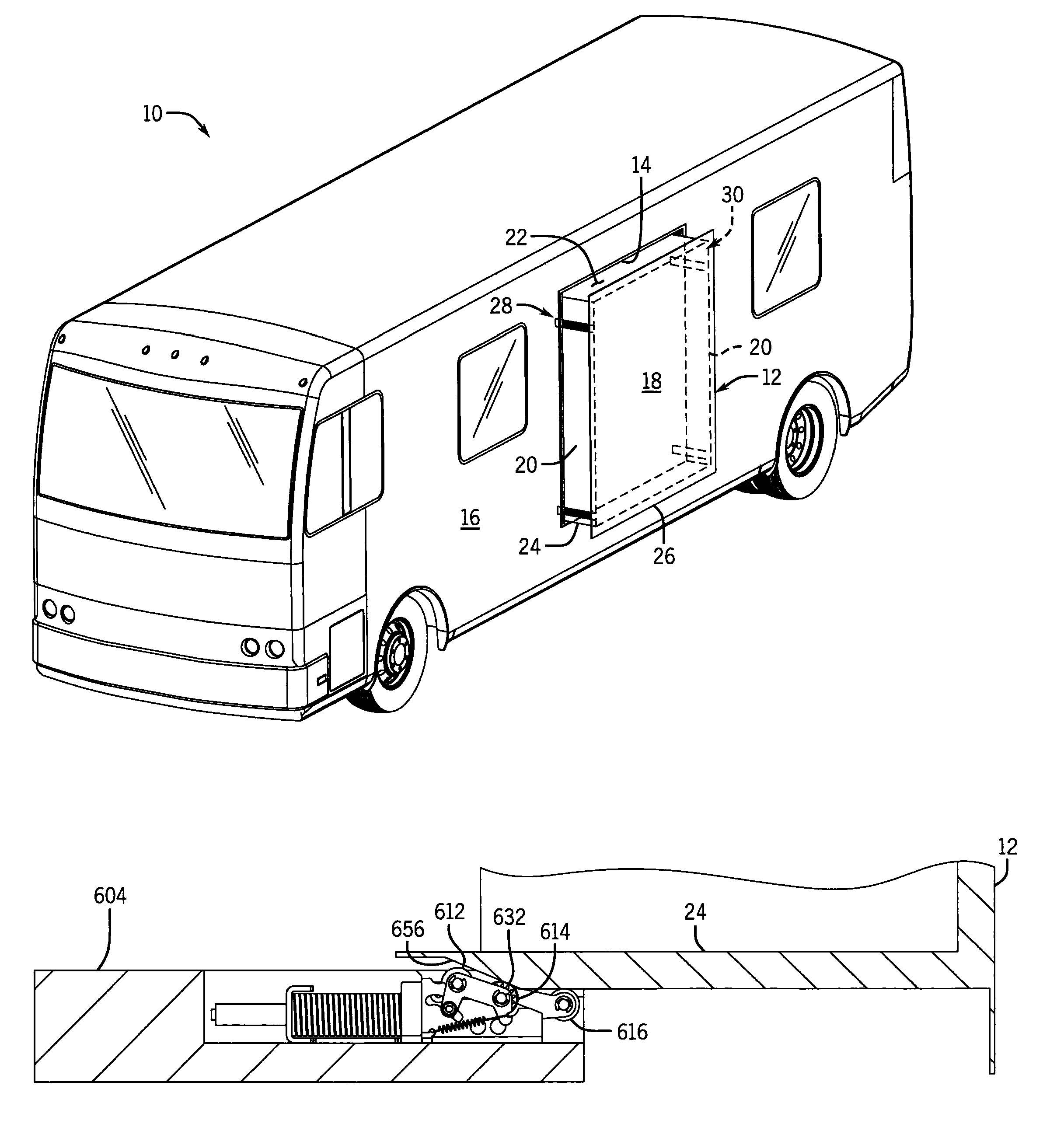
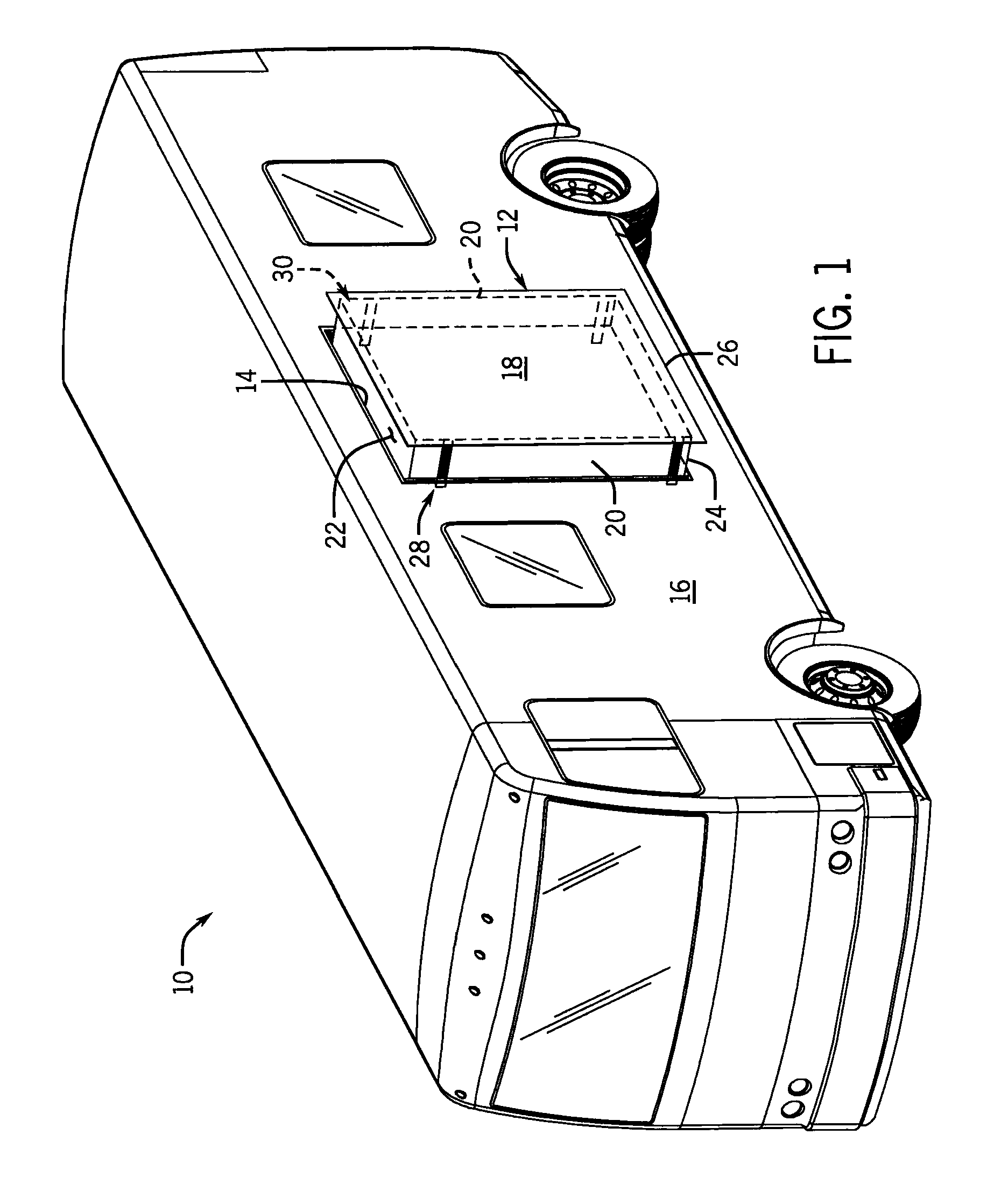
[0017]In another preferred aspect, the apparatus compensates for variations in spacing between the wall of the slide-out room and a perimeter of an opening in the side wall of the vehicle in which the slide-out room moves that occur as the slide-out room moves.
[0019]In another preferred aspect; the present invention provides for extending a slide-out room in a flat floor mechanism in which the room is lowered to the floor level of the vehicle without applying shear stresses on the gaskets.
[0020]In another preferred aspect, applying an in-wall mounted mechanism of the invention to a flush floor room provides versatility in the sequence of operation in going between the retracted elevated position and the extended lowered position. In one aspect, the sequence may be, starting from full retraction, to extend the slide-out room to a position nearly fully extended but that is just short of compressing the gaskets, then drop the room and then extend the rest of the way to compress the interior gaskets. This produces a motion that is shaped like a square Z.

Problems solved by technology

As such, the gear racks are typically skewed relative to the drive direction, which in turn may cause several problems.
First, the gear racks may simply move away from and disengage the pinions as the slide-out room moves.
Second, if the drive mechanism includes some type of feature that attempts to hold the gear rack in engagement with the pinion (for example, a pinion support bracket that engages the gear rack), the slide-out room wall may bend or deform because the rack urges it away from its manufactured position.
However, these designs introduce yet another problem.
In particular, when the vehicle comes to a stop, the large mass of the room may cause the room to shift over the clearance space, and the pinion mounting bracket may abruptly strike the support channel.
Such an action could damage the drive mechanism and could be relatively loud for the vehicle's occupants.
This problem is difficult to address because of the pinion mounting bracket's position within the support channel.
Furthermore, even if the mounting bracket can be accessed, fixing the bracket in the transverse direction again causes the original problem of the gear rack disengaging the pinion.
As another example of the limitations of rack-and-pinion drive mechanisms, the components that support the weight of the slide-out room are also disposed within the aperture and are typically relatively small due to the limited space.
These small supports can only carry a relatively small load, which essentially limits wall mounted rack-and-pinion mechanisms to use with relatively small and light slide-out rooms.
The slide-out room walls typically comprise a light-weight (and low-strength) material such as wood and, as such, the slide-out room walls can only carry a relatively small load.
This again limits wall mounted rack-and-pinion mechanisms to use with relatively small and light slide-out rooms.
Another drawback of wall mounted rack-and-pinion mechanisms is that the slide-out room typically only moves horizontally between the retracted position and the extended position and vice versa.
As yet another example of the limitations of rack-and-pinion drive mechanisms, a speed reducer (for example, a gearbox) connecting a drive motor to the pinion is not sufficient for inhibiting unintentional movement of the slide-out room while the vehicle travels, or to maintain the seals in compression over extended periods of time when the vehicle is parked.
That is, the speed reducer provides a relatively large reduction ratio and is difficult to back-drive.
Nevertheless, the speed reducer may be back-driven by the large forces imparted by the slide-out room when the vehicle accelerates or turns, or wind or other lateral forces applied to the vehicle over time even if stationary.
As such, the slide-out room may unintentionally move out or in.

Method used


Image

  • Slide-out room system having wall-mounted drive mechanisms
  • Slide-out room system having wall-mounted drive mechanisms
  • Slide-out room system having wall-mounted drive mechanisms

Examples


second embodiment

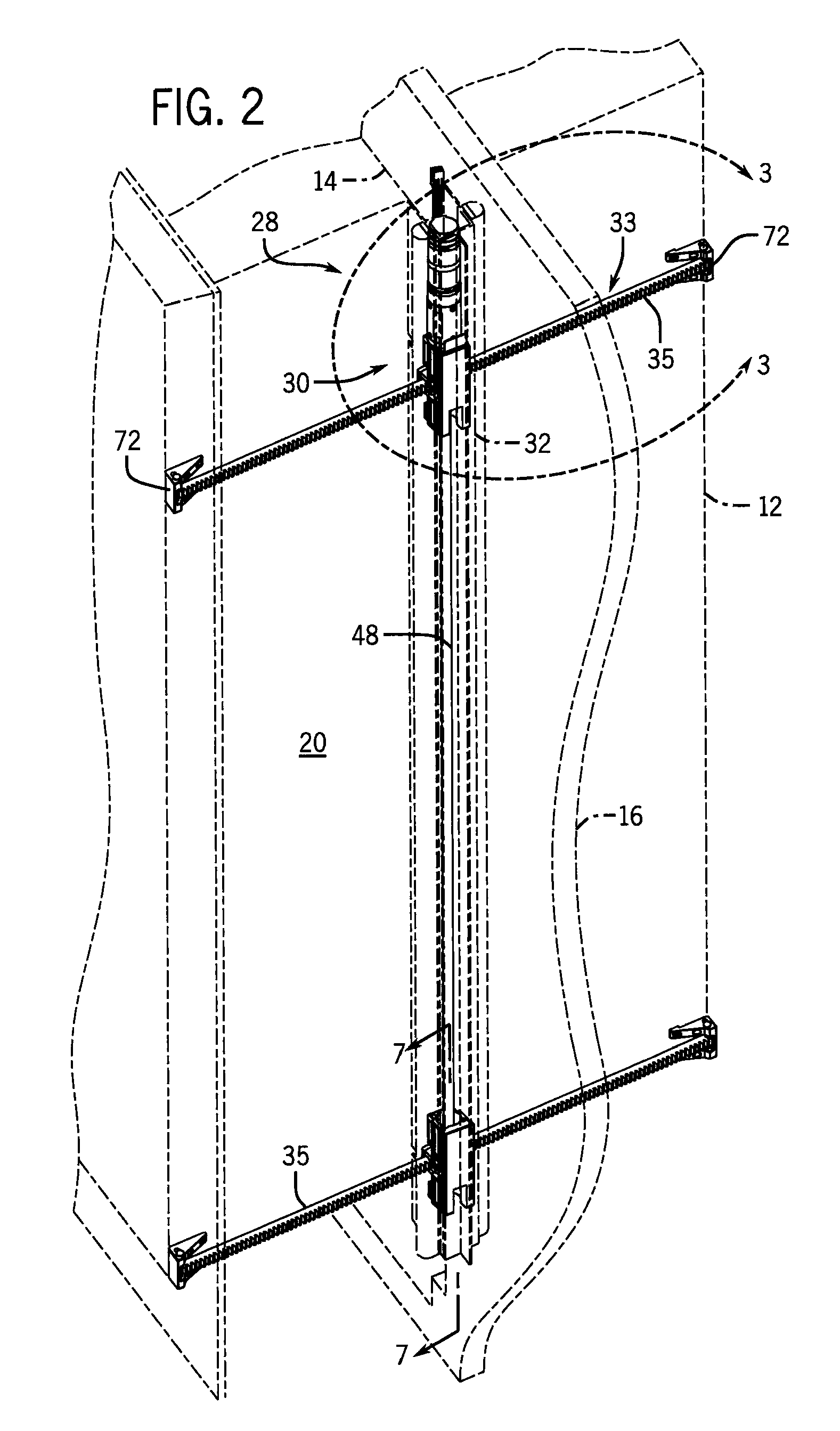
[0099]Turning now to FIG. 10, the drive mechanism 130 is generally as described above. However, the support channel 132 includes one or more lips 134 that connect to an edge proximate the slide-out room side wall 120 and extend in the drive direction. The lips 134 also extend between the drive support 142 and the slide-out room side wall 120, or “wrap” around the drive support 142, to inhibit the drive support 142 from moving out of the channel 132 in the transverse direction. However, the lips 134 permit the drive support 142 to float in the elevation direction as described above.

third embodiment

[0100]Referring to FIG. 11, the drive mechanism 230 is also generally as described above. However, the support channel 232 and the drive support 242 include an interface 234 proximate the rear wall of the channel 232 to connect the two components. As shown in the figures, the interface 234 may have a dovetail shape. Other shapes may be used provided that they inhibit the drive support 242 from moving out of the channel 232 in the transverse direction and permit the drive support 242 to float in the elevation direction.

[0101]Referring to FIGS. 12-18 and as briefly described above, in some embodiments the ability of the drive supports 42 to float in the elevation direction permits the slide-out room 12 to be used as a flush floor room. As the name implies, the floor of such a flush floor room moves downwardly and is level with the floor of the vehicle in the extended position (see FIG. 18). To facilitate such downward movement of the slide-out room 12, the vehicle 10 mounts one or mor...


PUM


Abstract

An apparatus for moving a slide-out room disposed in an aperture of a side wall of a vehicle from a retracted position to an extended position in a drive direction. The apparatus includes a drive assembly supported by the side wall of the vehicle and a driven assembly driven by the drive assembly. The driven assembly is connected to a wall of the slide-out room such that the slide-out room moves with the driven assembly from the retracted position to the extended position in the drive direction and the driven assembly is movable in a transverse direction generally perpendicular to the drive direction relative to the wall of the slide-out room. The room is extended and retracted horizontally and moved between upper and lower positions vertically in a square Z or square h pattern.

Description

CROSS-REFERENCE TO RELATED APPLICATIONS[0001]This application claims the benefit of U.S. Provisional Application No. 61 / 775,020 filed Mar. 8, 2013, and is a continuation-in-part of U.S. patent application Ser. No. 13 / 660,619 filed Oct. 25, 2012, and U.S. patent application Ser. No. 13 / 660,739 filed Oct. 25, 2012, which claim the benefit of U.S. Provisional Patent Application No. 61 / 664,542 filed Jun. 26, 2012, U.S. Provisional Patent Application No. 61 / 647,908 filed May 16, 2012, U.S. Provisional Patent Application No. 61 / 565,730 filed Dec. 1, 2011, and U.S. Provisional Patent Application No. 61 / 551,719 filed Oct. 26, 2011, the disclosures of all of which are hereby incorporated by reference for all purposes.STATEMENT REGARDING FEDERALLY SPONSORED RESEARCH OR DEVELOPMENT[0002]Not applicable.FIELD OF THE INVENTION[0003]This invention generally relates to slide-out rooms of recreational vehicles, and more particularly, slide-out rooms having multiple compact wall-mounted drive mechani...

Claims


Application Information

Patent Timeline
Patent Type & Authority Patents(United States)
IPC IPC(8): B60P3/34
CPCB60P3/34
Inventor KREIL, CRAIG J.
Owner LIPPERT COMPONENTS MFG INC
Learn More