
Auto-alignment of image sensors in a multi-camera system

a multi-camera system and image sensor technology, applied in the field of digital cameras, can solve the problems of incorrect depth determination of object depth, rolling shutter artifacts, and capture objects moving relative to an image fram

Active Publication Date: 2015-03-24
GOPRO
View PDF4 Cites 104 Cited by
  • Summary
  • Abstract
  • Description
  • Claims
  • Application Information

AI Technical Summary

Benefits of technology

The patent text discusses a system and method for synchronizing multiple cameras to capture images. The system uses overlapping fields of view and edge detection to align the cameras and capture images at the same time. This helps to avoid blurring and incorrect depth information in the resulting 3D images. The technical effect of the patent text is to provide a more reliable and efficient way to capture synchronized images from multiple cameras.

Problems solved by technology

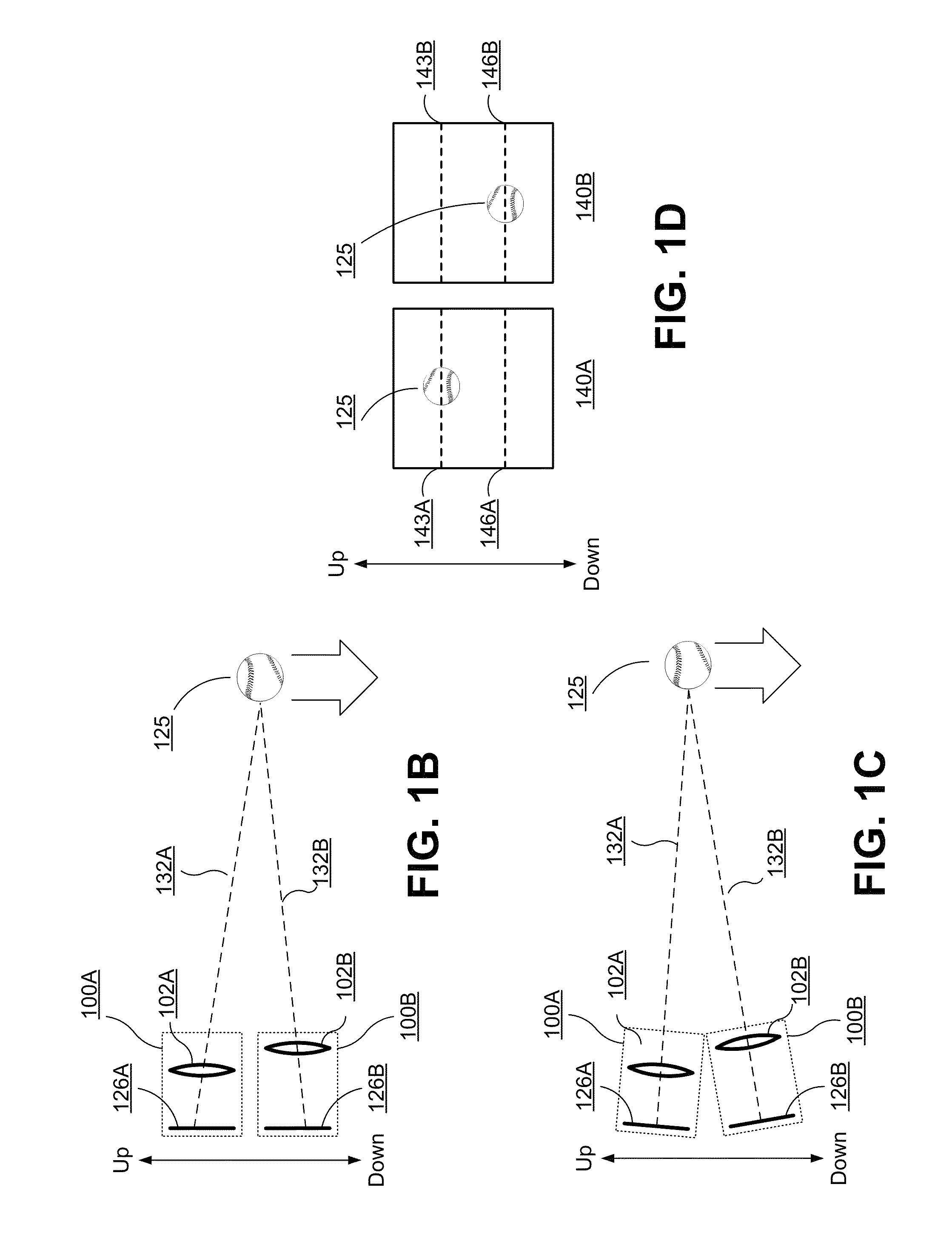
Otherwise, capture objects moving relative to an image frame can appear at an incorrect depth in the resulting 3D image.
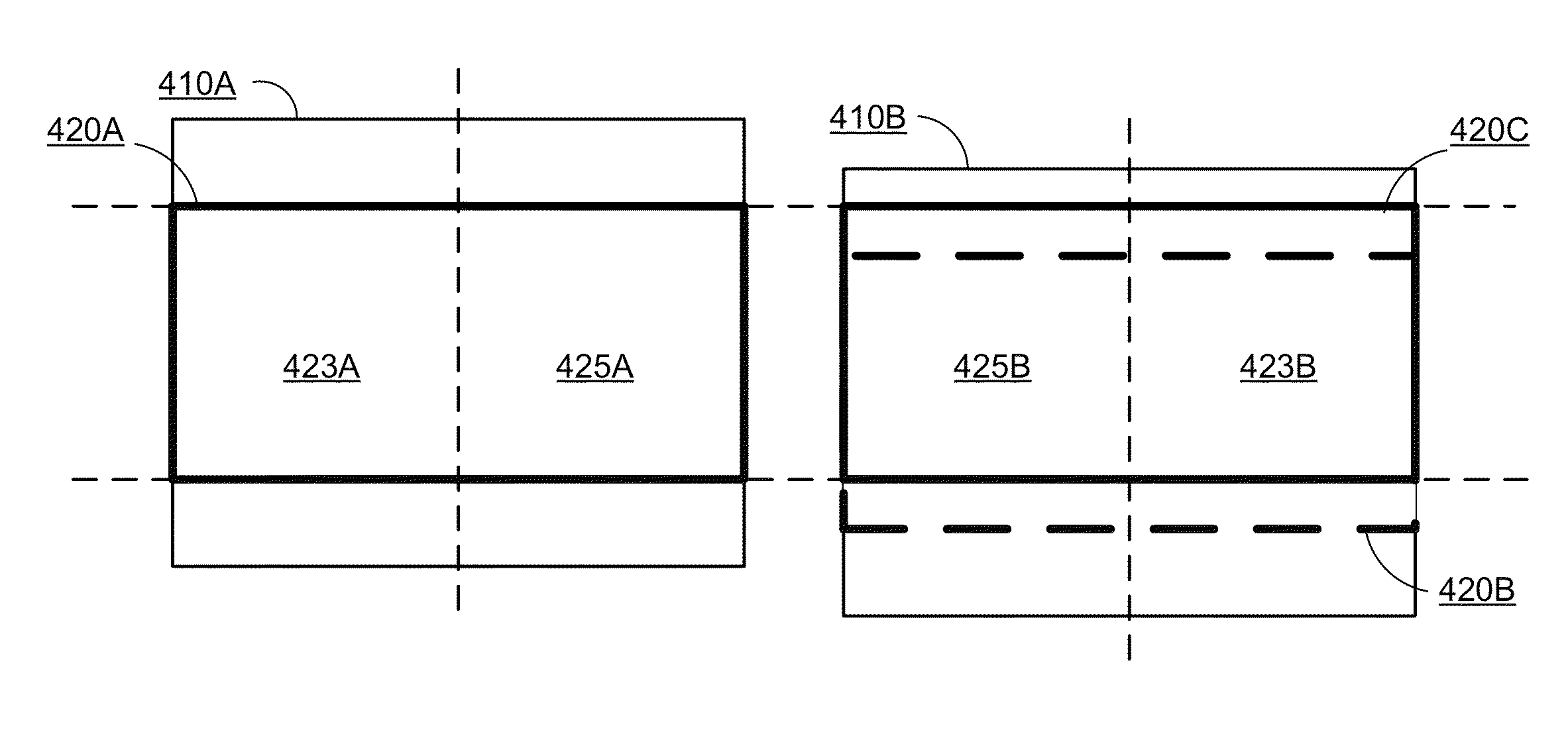
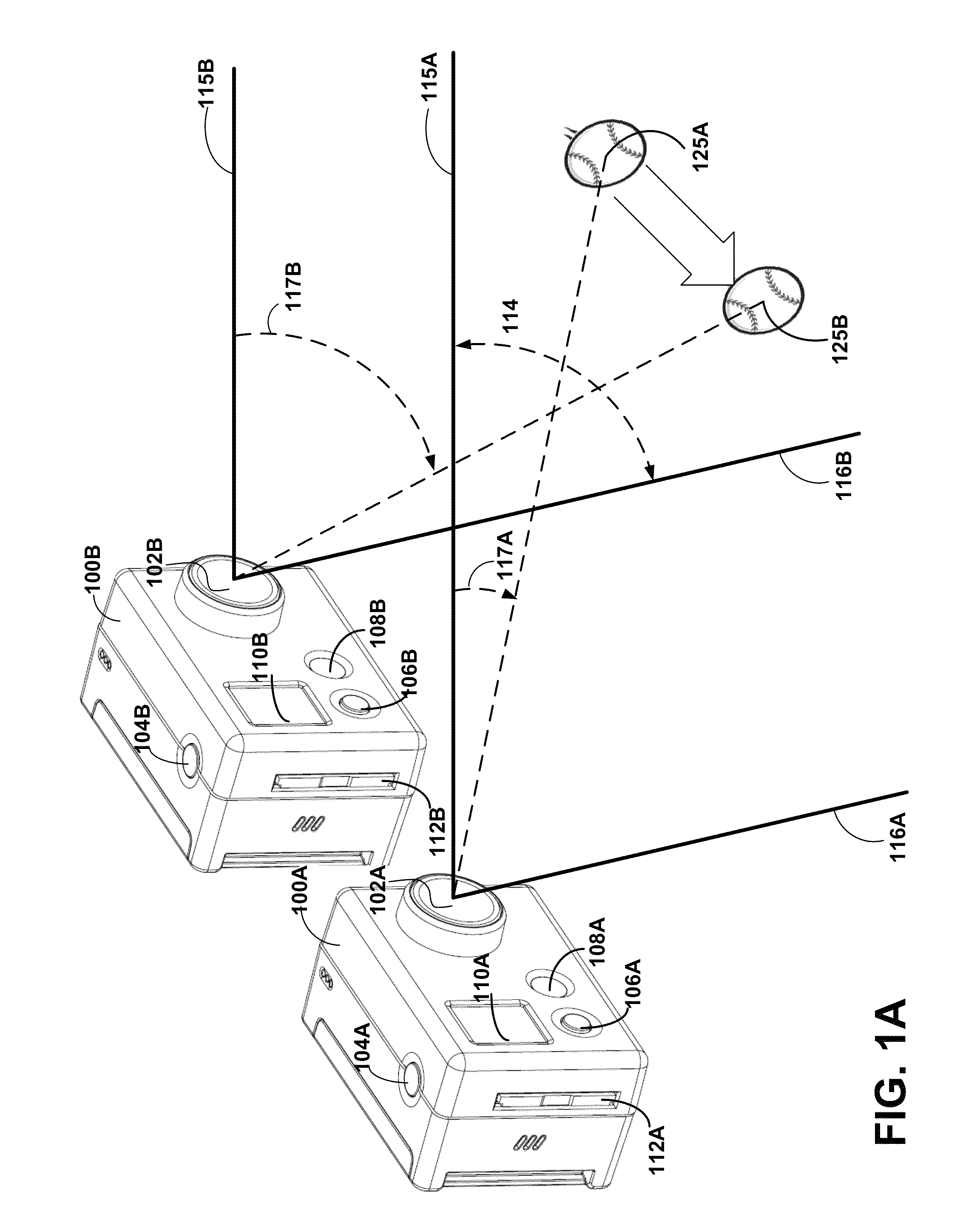
When the rolling shutters of two cameras are misaligned, capturing the 2D images even simultaneously can result in rolling shutter artifacts and incorrect object depth determinations, as different portions of a scene are captured at different times. If the cameras do not capture the same portion of the scene at the same time, then any moving elements of the scene may appear blurred.
To synchronize image capture, cameras containing the image sensors can be aligned along the direction of the rolling shutter using a six-axis pan-tilt camera mount, but aligning the cameras by this method is a time-consuming task, even for an experienced photographer.

Method used


Image

  • Auto-alignment of image sensors in a multi-camera system
  • Auto-alignment of image sensors in a multi-camera system
  • Auto-alignment of image sensors in a multi-camera system

Examples


Embodiment Construction

[0017]The Figures (FIGS.) and the following description relate to preferred embodiments by way of illustration only. It should be noted that from the following discussion, alternative embodiments of the structures and methods disclosed herein will be readily recognized as viable alternatives that may be employed without departing from the principles of what is claimed.

[0018]Reference will now be made in detail to several embodiments, examples of which are illustrated in the accompanying figures. It is noted that wherever practicable similar or like reference numbers may be used in the figures and may indicate similar or like functionality. The figures depict embodiments of the disclosed system (or method) for purposes of illustration only. One skilled in the art will readily recognize from the following description that alternative embodiments of the structures and methods illustrated herein may be employed without departing from the principles described herein.

Configuration Overvie...


PUM


Abstract

A pair of cameras having an overlapping field of view is aligned based on images captured by image sensors of the pair of cameras. A pixel shift is identified between the images. Based on the identified pixel shift, a calibration is applied to one or both of the pair of cameras. To determine the pixel shift, the camera applies correlation methods including edge matching. Calibrating the pair of cameras may include adjusting a read window on an image sensor. The pixel shift can also be used to determine a time lag, which can be used to synchronize subsequent image captures.

Description

BACKGROUND[0001]1. Field of Art[0002]The disclosure generally relates to the field of digital cameras, and more particularly to capturing synchronized images from multiple cameras.[0003]2. Description of the Related Art[0004]Digital cameras capture images using an electronic image sensor. Example image sensors use CCD (charge-coupled device) or CMOS (complementary metal-oxide semiconductor) technology. A CMOS image sensor contains photodiodes corresponding to pixels of a captured image. In one configuration, the photodiodes are arranged in rows and columns. To capture an image, successive rows of photodiodes are exposed and read over time. The direction in which rows of photodiodes are exposed over time is the rolling shutter direction. For example, if an image sensor reads a row of photodiodes after reading the row of photodiodes above it, then the image sensor has a downward rolling shutter direction. Portions of the image along the rolling shutter direction are exposed at later t...

Claims


Application Information

Patent Timeline
Patent Type & Authority Patents(United States)
IPC IPC(8): H04N13/02H04N13/239H04N17/00H04N23/90
CPCH04N17/002H04N13/239H04N13/246H04N13/296H04N23/698H04N25/531H04N23/90H04N23/66H04N5/265H04N13/00
Inventor MACMILLAN, TIMOTHYCAMPBELL, SCOTT PATRICKNEWMAN, DAVID A.SUN, YAJIE
Owner GOPRO
Learn More