
Methods and systems for non-destructive composite evaluation and repair verification

a composite evaluation and repair verification technology, applied in the field of composite repair verification, can solve the problems of inability to produce the images required in many cases, inability to perform handheld scanning, and inability to perform inspections,

Active Publication Date: 2015-03-17
THE BOEING CO
View PDF7 Cites 29 Cited by
  • Summary
  • Abstract
  • Description
  • Claims
  • Application Information

AI Technical Summary

Benefits of technology

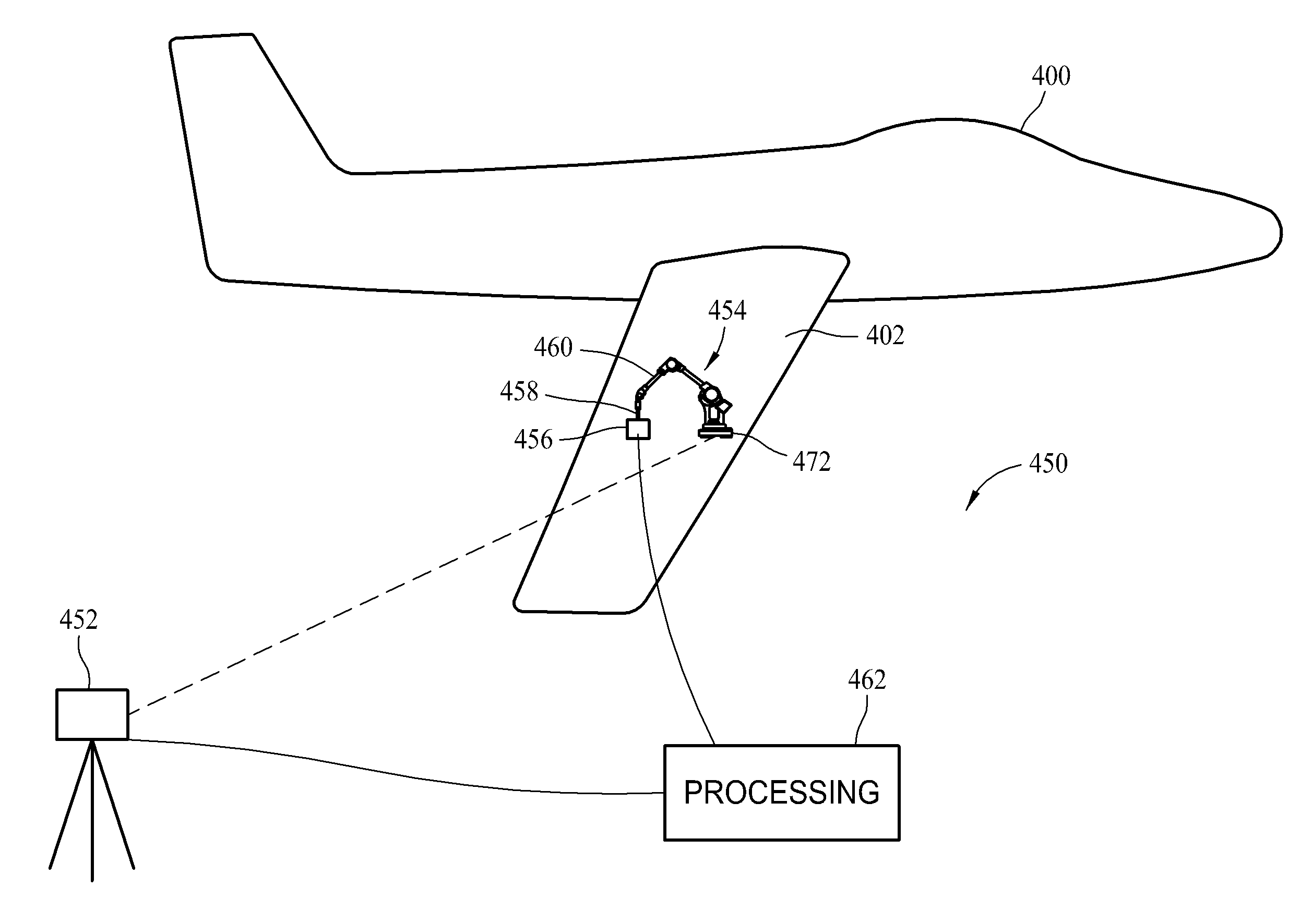
The patent describes a system for inspecting structures using a local positioning system and a six-degree-of-freedom digitizer. The digitizer is attached to the end of an articulating arm and has a sensor array for collecting scan samples of the structure. The system can determine the position of the scanning device in relation to the structure and use it to create a 3D representation of the structure's scan volume. The technical effect of this system is that it allows for non-destructive inspection of structures with high accuracy and efficiency.

Problems solved by technology

Currently validation of such repairs can only be performed using expensive equipment.
However, handheld scanning is very slow and cannot produce the images required in many cases, for example, the measurement of porosity that is utilized in composite repairs.
Moreover, such phased array UT systems are very expensive and somewhat complex.
The MAUS scanner is also expensive, complicated to operate (using it requires specialized skills), and further requires two people to attach and run.
As such, few potential users can afford it, and it is limited to minimally contoured structures because of the design of the flexible track and scanner arm, for example, it cannot do leading edges, or corners of structures having a radius.
While the rapid scan tool collects image data quickly, the cost and complexity of the system limit broad usage.
Further, it is not designed for highly contoured surfaces, and has no three-dimensional imaging capability.
Systems with positional encoders are slow, and do not have the spatial resolution required for composite repair validation and porosity measurement.
Further, they do not include a three-dimensional imaging capability.
The FAST applies to many inspection applications, but the IMUs it is based upon do not currently have the spatial resolution for zoned porosity measurements in composite repairs.

Method used


Image

  • Methods and systems for non-destructive composite evaluation and repair verification
  • Methods and systems for non-destructive composite evaluation and repair verification
  • Methods and systems for non-destructive composite evaluation and repair verification

Examples


Embodiment Construction

[0021]The described embodiments are directed to methods and systems that combine three-dimensional metrology, non-destructive evaluation (NDE) array sensor technology, a local positioning system (LPS) and a rapid attachment capability to produce a low cost, high resolution, portable, three-dimensional NDE scanning process for verification of composite repairs and validation of other structures.

[0022]The embodiments enable more efficient aircraft composite repair by making validation of the repair simpler and more cost-effective than is presently possible. In embodiments, and as described in further detail below, attachment of an articulated measurement device to the composite material to be validated, allows free-form, high resolution scanning and imaging of interior damage / defects in composites. Validation of repairs and verification of other structures is therefore provided, even for structures with highly complex shapes. As further described herein, the system uses a local positi...


PUM


Abstract

A non-destructive inspection system for a structure is described. The inspection system includes a local positioning system (LPS) configured for determining position and orientation of objects relative to a structure coordinate system, a six degree-of-freedom digitizer operable for at least one of temporary attachment to the structure and placement proximate the structure, a non-destructive sensor array, and a processing device.

Description

BACKGROUND[0001]The field of the disclosure relates generally to composite repair verification, and more specifically, to methods and systems for non-destructive composite evaluation and repair verification.[0002]With the increased usage of composites for aircraft structures, obtaining rapid, low-cost, yet high resolution non-destructive evaluation (NDE) data on in-service composite aircraft has become more important, and yet still remains a need within the aerospace industry. While damage assessment may be done with a lower resolution scanner or handheld single transducer system, composite repair verification requires high spatial resolution to quantify porosity. Currently only scanned pulse echo ultrasound is capable of providing the zoned porosity measurements required for validating composite scarfed and bonded repairs. Currently validation of such repairs can only be performed using expensive equipment.[0003]One existing validation tool includes a handheld ultrasonic transducer...

Claims


Application Information

Patent Timeline
IPC IPC(8): G01C9/00
CPCB64F5/60G01B17/06G01B21/04G01C15/00G01N27/90G01N29/07G01N29/11G01N29/226G01N29/262G01N2291/0231G01N2291/2694G01S15/8915G01S15/8936G01S15/899G01S15/8993G01S15/86
Inventor MOTZER, WILLIAM P.GEORGESON, GARY E.LEA, SCOTT W.TROY, JAMES J.
Owner THE BOEING CO
Learn More