Display device
a display device and display technology, applied in the field of display devices, can solve the problems of low responsivity of liquid crystal display devices with respect to video data, caused by moving image blurring (pseudo-contour), etc., and achieve the effect of suppressing moving image blurring, improving the color purity of emission light colors, and easy configuration of display devices with excellent display quality
- Summary
- Abstract
- Description
- Claims
- Application Information
AI Technical Summary
Benefits of technology
Problems solved by technology
Method used
Image

Examples
embodiment 1
[0055][Embodiment 1]
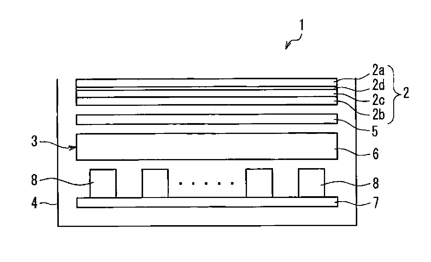
[0056]FIG. 1 is a view illustrating a schematic configuration of a liquid crystal display device according to Embodiment 1 of the present invention. In the drawing, a liquid crystal display device 1 of the present embodiment is provided with a liquid crystal panel (LCD) 2 as a display part that is located with an upper side of FIG. 1 defined as a viewing side (display surface side) and a backlight device 3 as a backlight part that is disposed on a non-display surface side of the liquid crystal panel 2 (the lower side in the drawing) and that generates illumination light for illuminating the liquid crystal panel 2. Further, in the present embodiment, the liquid crystal panel 2 and the backlight device 3 are contained integrally as a transmission-type liquid crystal display device 1 inside a housing 4. Further, the liquid crystal display device 1 of the present embodiment is provided with a later-described video generating device (control part) that controls drive ...
embodiment 2
[0113][Embodiment 2]
[0114]FIG. 10 is a block diagram showing a specific configuration of a video generating device in a liquid crystal display device according to Embodiment 2 of the present invention. In the drawing, the present embodiment mainly differs from the above-described Embodiment 1 in that the video generating device is provided with a lighting auxiliary part that corrects an instruction signal for increasing the luminance of light-emitting diodes based on the decided ON or OFF period. The common elements as those in the above-described Embodiment 1 are denoted with the same reference numerals, and the explanation will not be repeated.
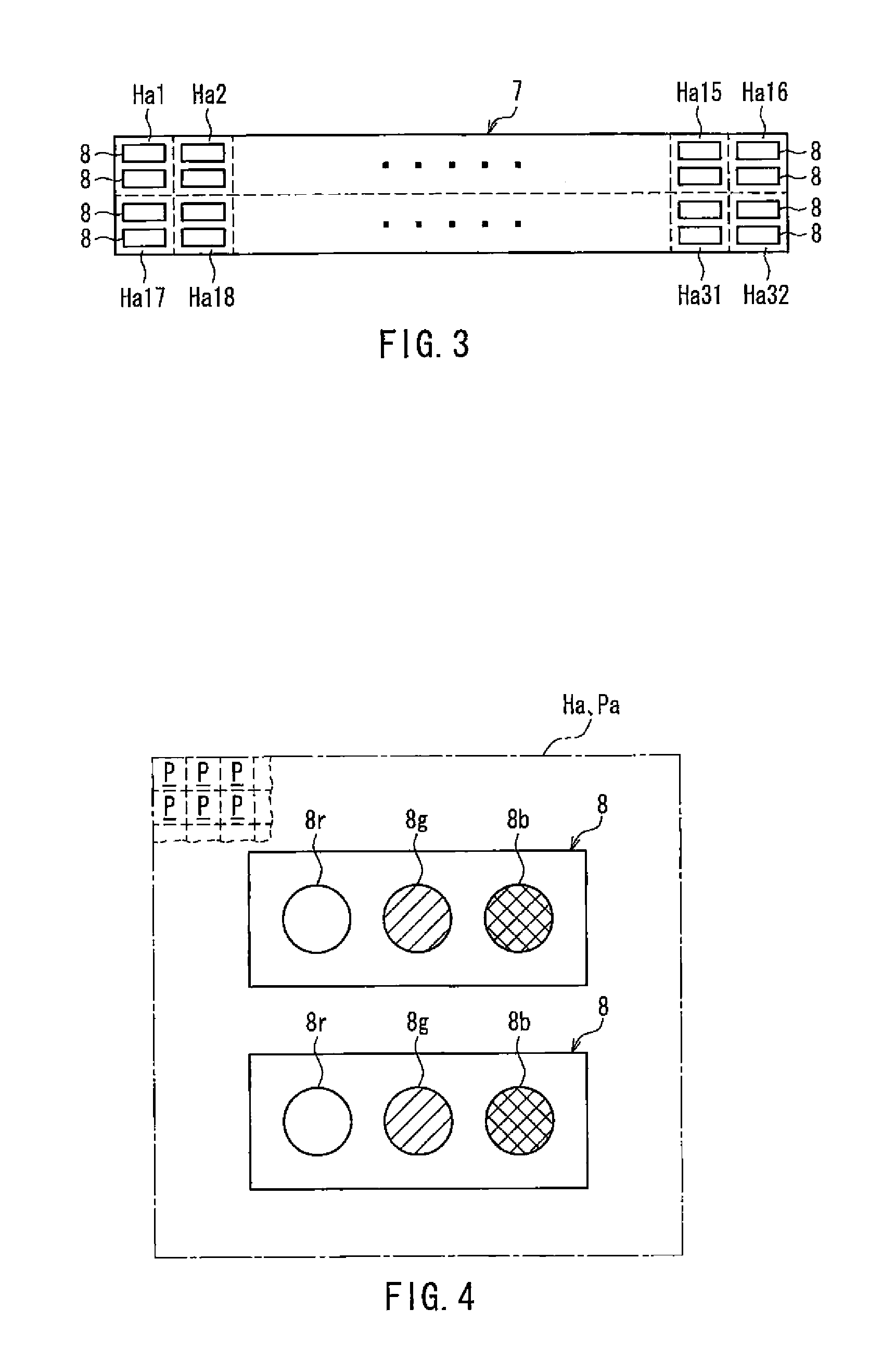
[0115]As shown in FIG. 10, in a video generating device 30 of the present embodiment, a lighting auxiliary part 31 is connected to the lighting time setting part 21. The lighting auxiliary part 31 decides whether or not to increase the luminance of the respective light-emitting diodes 8r, 8g, 8b based on LED video data set at the lighting ti...
embodiment 3
[0127][Embodiment 3]
[0128]FIG. 12 is a block diagram showing a specific configuration of a video generating device in a liquid crystal display device according to Embodiment 3 of the present invention. In the drawing, the present embodiment mainly differs from the above-described Embodiment 2 in that the video generating device is provided with a lighting auxiliary part that corrects an instruction signal for increasing the luminance of light-emitting diodes on the illumination area basis, based on the decided ON or OFF period. The common elements as those in the above-described Embodiment 2 are denoted with the same reference numerals, and the explanation will not be repeated.
[0129]As shown in FIG. 12, in a video generating device 30′ of the present embodiment, a lighting auxiliary part 31′ is connected to the lighting time setting part 21. The lighting auxiliary part 31′ decides whether or not to increase the luminance of the respective light-emitting diodes 8r, 8g, 8b on the illu...
PUM
| Property | Measurement | Unit |
|---|---|---|
| frame frequency | aaaaa | aaaaa |
| time | aaaaa | aaaaa |
| length | aaaaa | aaaaa |
Abstract
Description
Claims
Application Information
 - R&D
- Intellectual Property
- Life Sciences
- Materials
- Tech Scout
- Unparalleled Data Quality
- Higher Quality Content
- 60% Fewer Hallucinations
Browse by: Latest US Patents, China's latest patents, Technical Efficacy Thesaurus, Application Domain, Technology Topic, Popular Technical Reports.
© 2025 PatSnap. All rights reserved.Legal|Privacy policy|Modern Slavery Act Transparency Statement|Sitemap|About US| Contact US: help@patsnap.com