Driving force transmission apparatus
a transmission apparatus and driving force technology, applied in the direction of mechanical actuated clutches, couplings, fluid couplings, etc., can solve the problems of adverse influence on the turning performance and fuel economy, and the inability to obtain desirable clutch action of the clutch, so as to reduce the drag torque and improve the response of the clutch action of the main clutch
- Summary
- Abstract
- Description
- Claims
- Application Information
AI Technical Summary
Benefits of technology
Problems solved by technology
Method used
Image
Examples
first embodiment
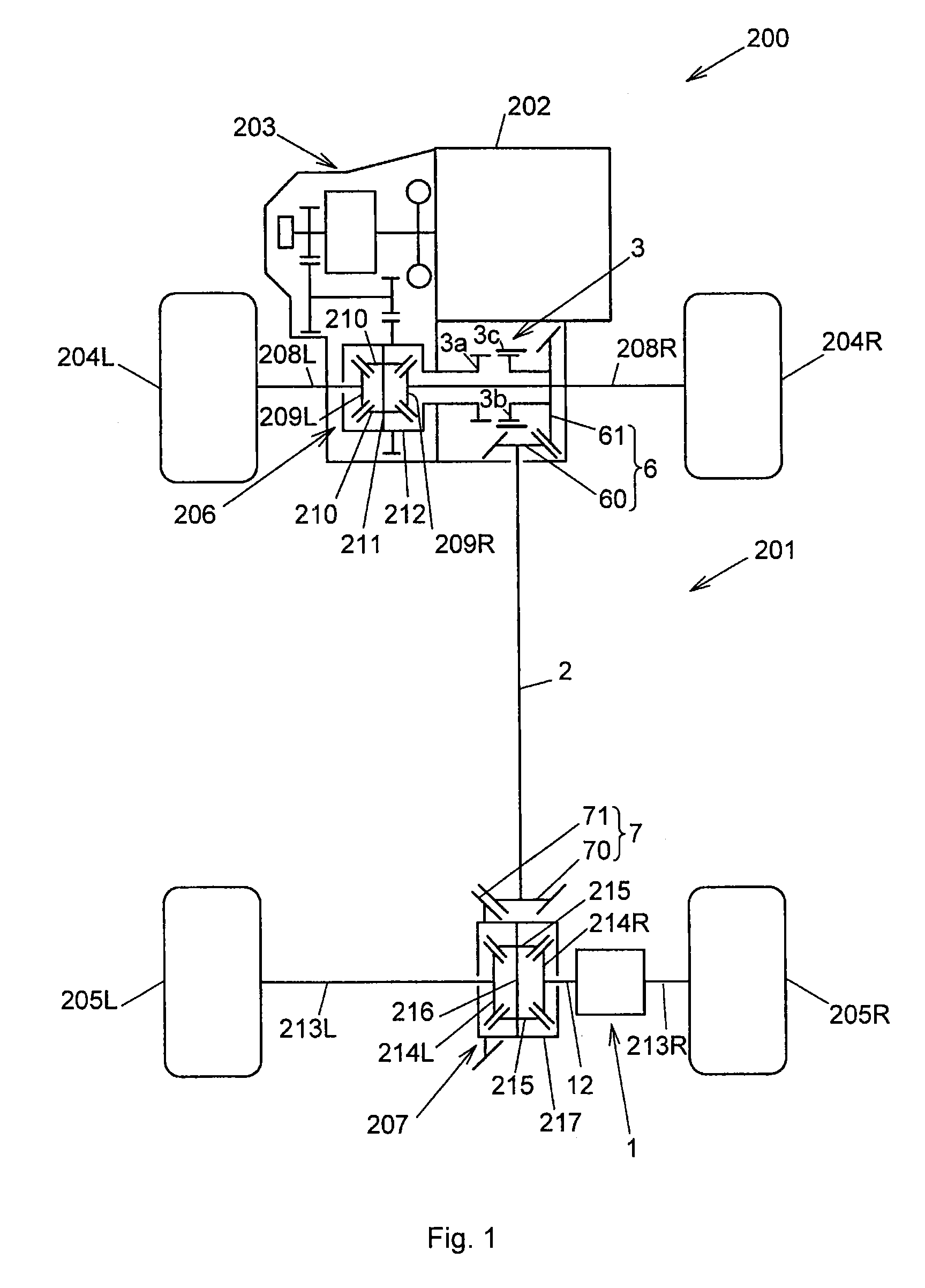
[0038]the invention will be described below. FIG. 1 schematically shows a four-wheel-drive vehicle 200. The four-wheel-drive vehicle 200 includes a driving force transmission system 201, an engine 202, a transmission 203, front wheels 204L, 204R that serve as main drive wheels, and rear wheels 205L, 205R that serve as auxiliary drive wheels.
[0039]The driving force transmission system 201 is arranged on a driving force transmission path that extends from the transmission 203 to the rear wheels 205L, 205R in the four-wheel-drive vehicle 200, together with a front differential 206 and a rear differential 207. The driving force transmission system 201 is mounted on a vehicle body (not shown) of the four-wheel-drive vehicle 200.
[0040]The driving force transmission system 201 includes a driving force transmission apparatus 1, a propeller shaft 2, and a driving force interrupting device 3. The driving force transmission system 201 is configured to be able to shift the four-wheel-drive vehi...
second embodiment
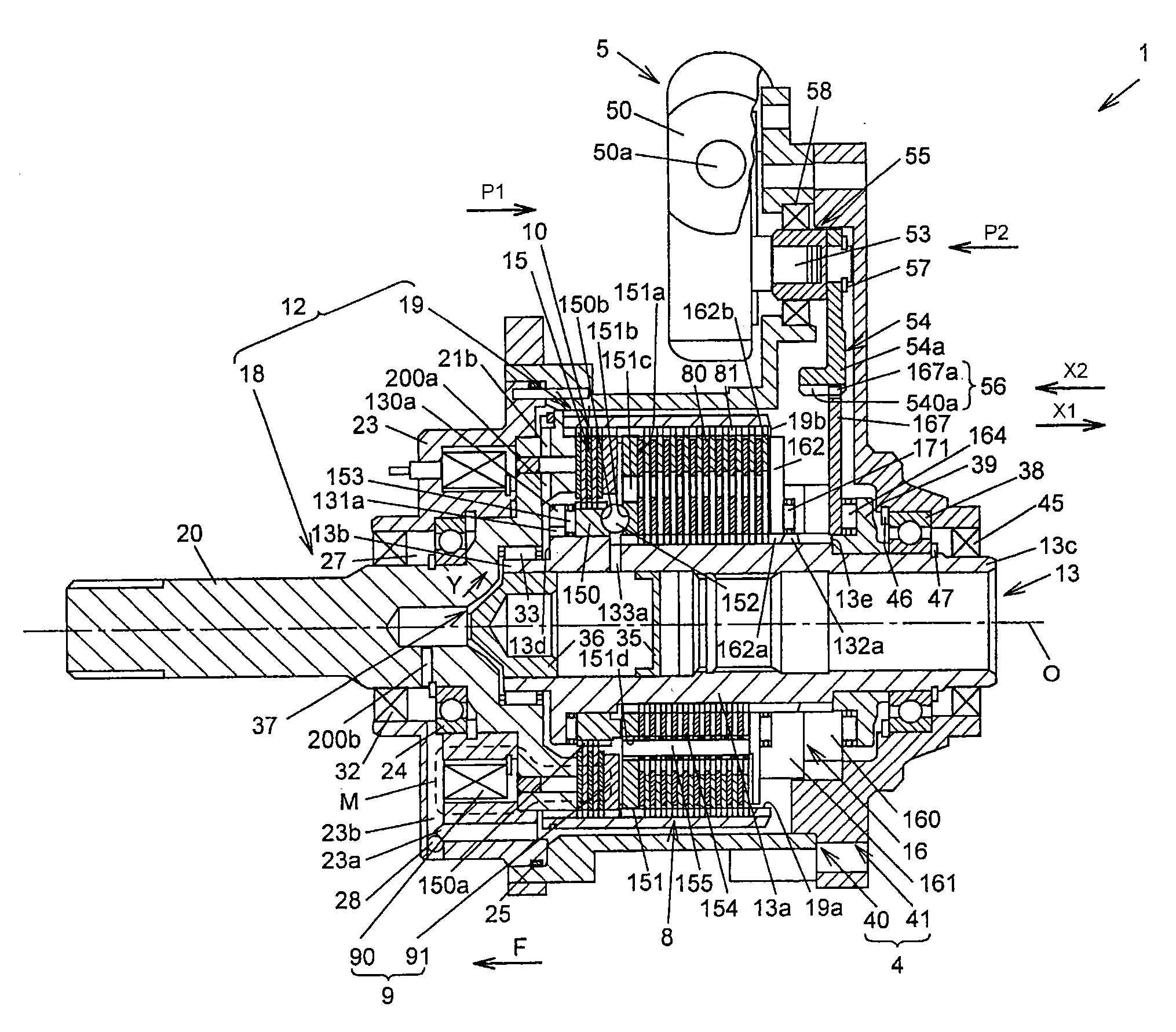
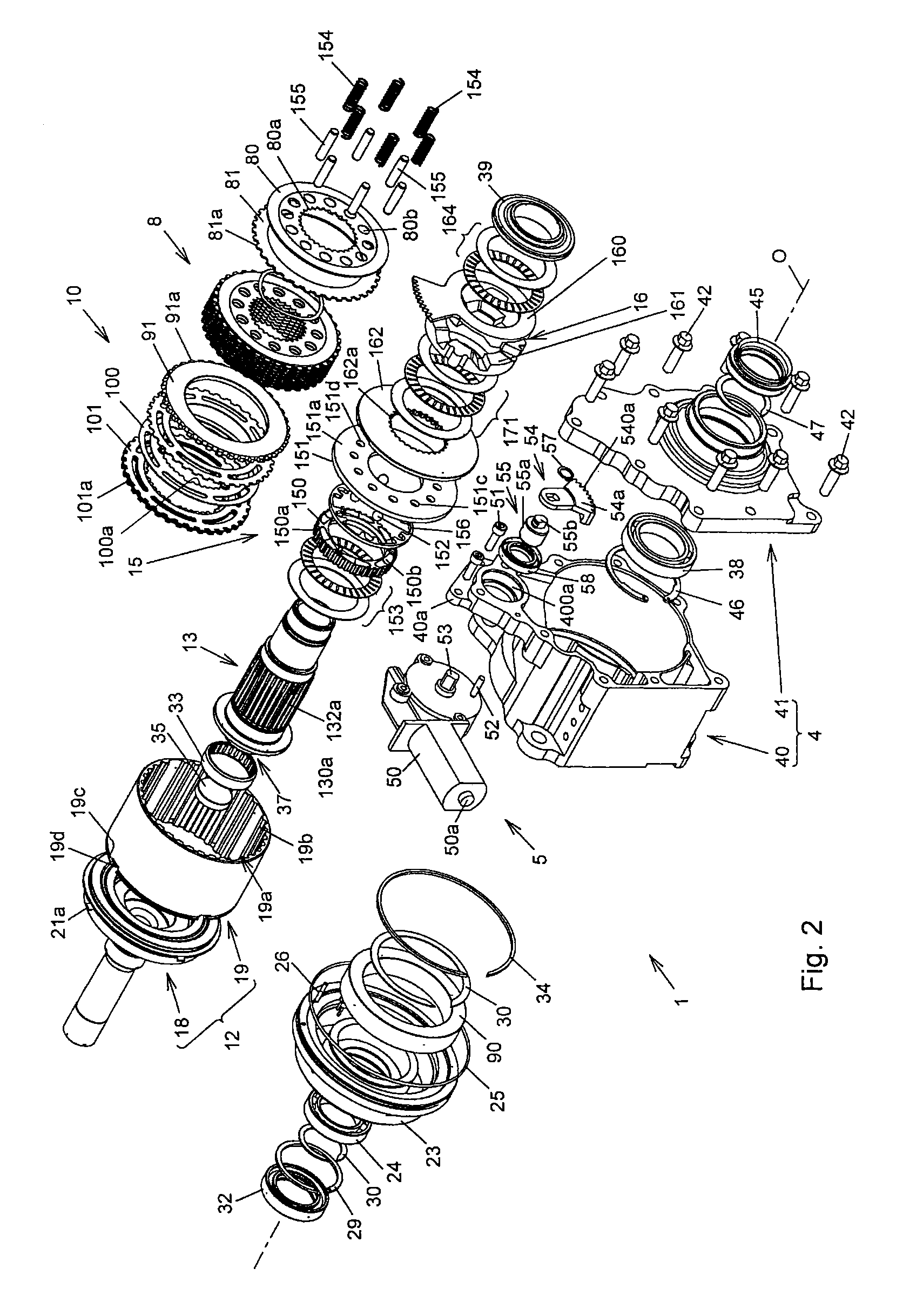
[0133]Next, a driving force transmission apparatus 190 according to the invention will be described with reference to FIG. 9 to FIG. 13 and FIG. 14A and FIG. 14B. FIG. 9 and FIG. 10 show the entirety of the driving force transmission apparatus. FIG. 11 shows a rear housing. FIG. 12 shows a first element of the rear housing. FIG. 13 shows a second element of the rear housing. FIG. 14A and FIG. 14B show a third element of the rear housing. In FIG. 9 to FIG. 13 and FIG. 14A and FIG. 14B, the components having functions the same as or equivalent to those in FIG. 2 and FIG. 3 are denoted by the same reference numerals as those in FIG. 2 and FIG. 3, and the detailed description thereof is omitted.
[0134]As shown in FIG. 9 and FIG. 10, the driving force transmission apparatus 190 according to the second embodiment of the invention differs from the driving force transmission apparatus 1 according to the first embodiment (shown in FIG. 3) where the rear housing 19 is of an open type so that t...
PUM
 Abstract
Description
Claims
Application Information
 - R&D
- Intellectual Property
- Life Sciences
- Materials
- Tech Scout
- Unparalleled Data Quality
- Higher Quality Content
- 60% Fewer Hallucinations
Browse by: Latest US Patents, China's latest patents, Technical Efficacy Thesaurus, Application Domain, Technology Topic, Popular Technical Reports.
© 2025 PatSnap. All rights reserved.Legal|Privacy policy|Modern Slavery Act Transparency Statement|Sitemap|About US| Contact US: help@patsnap.com


