
Efficient computation of wave equation migration angle gathers

a technology of migration angle and computation method, applied in the field of geophysical prospecting, can solve the problems of less useful than angle gathers, more expensive than wem, and difficult to efficiently produce common reflection angle gathers with either method

Active Publication Date: 2015-02-24
EXXONMOBIL UPSTREAM RES CO
View PDF66 Cites 3 Cited by
  • Summary
  • Abstract
  • Description
  • Claims
  • Application Information

AI Technical Summary

Benefits of technology

The invention is a method for imaging seismic data from a subsurface region and producing common reflection angle or common azimuth gathers or producing gathers that are functions of both common reflection angles and common azimuth angles. The method involves computing the stress tensor and local particle velocity of the source side and receiver side at a multiply of image points, converting the direction of energy propagation to the direction of phase variation, and using this information to construct the reflection angle or the azimuth angle. The image value at each image point is computed from a cross correlation of a forward and backward propagated wavefield. The velocity model used in the process can be selected and the reflection angle bins can be determined based on the characteristics of the subsurface region. The invention allows for improved seismic imaging and interpretation in subterranean regions.

Problems solved by technology

This method can produce good images at all reflector dips, but is more expensive than WEM by a factor typically in the range of 4-10.
However it is not straightforward with either method to efficiently produce common reflection angle gathers.
It is also possible to work with surface offset gathers; however these are less useful than angle gathers in complex imaging situations because they do not handle multipathing.
This method has the disadvantage that it requires computation of a local Fourier transform, and is therefore not computationally efficient if angle gathers are required at many image points.
A further problem with this approach is that it requires the computation and storage of data volumes for each value of {right arrow over (h)}.
This approach may leads to impractical quantities of data, especially in 3D unless the 3D image space {right arrow over (x)} is sampled on a coarse grid.

Method used


Image

  • Efficient computation of wave equation migration angle gathers
  • Efficient computation of wave equation migration angle gathers
  • Efficient computation of wave equation migration angle gathers

Examples


Embodiment Construction

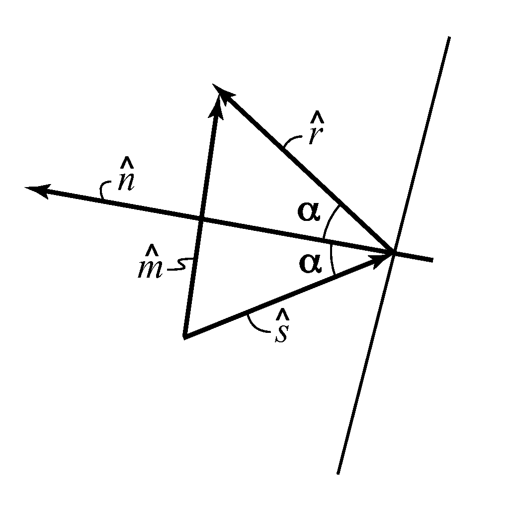
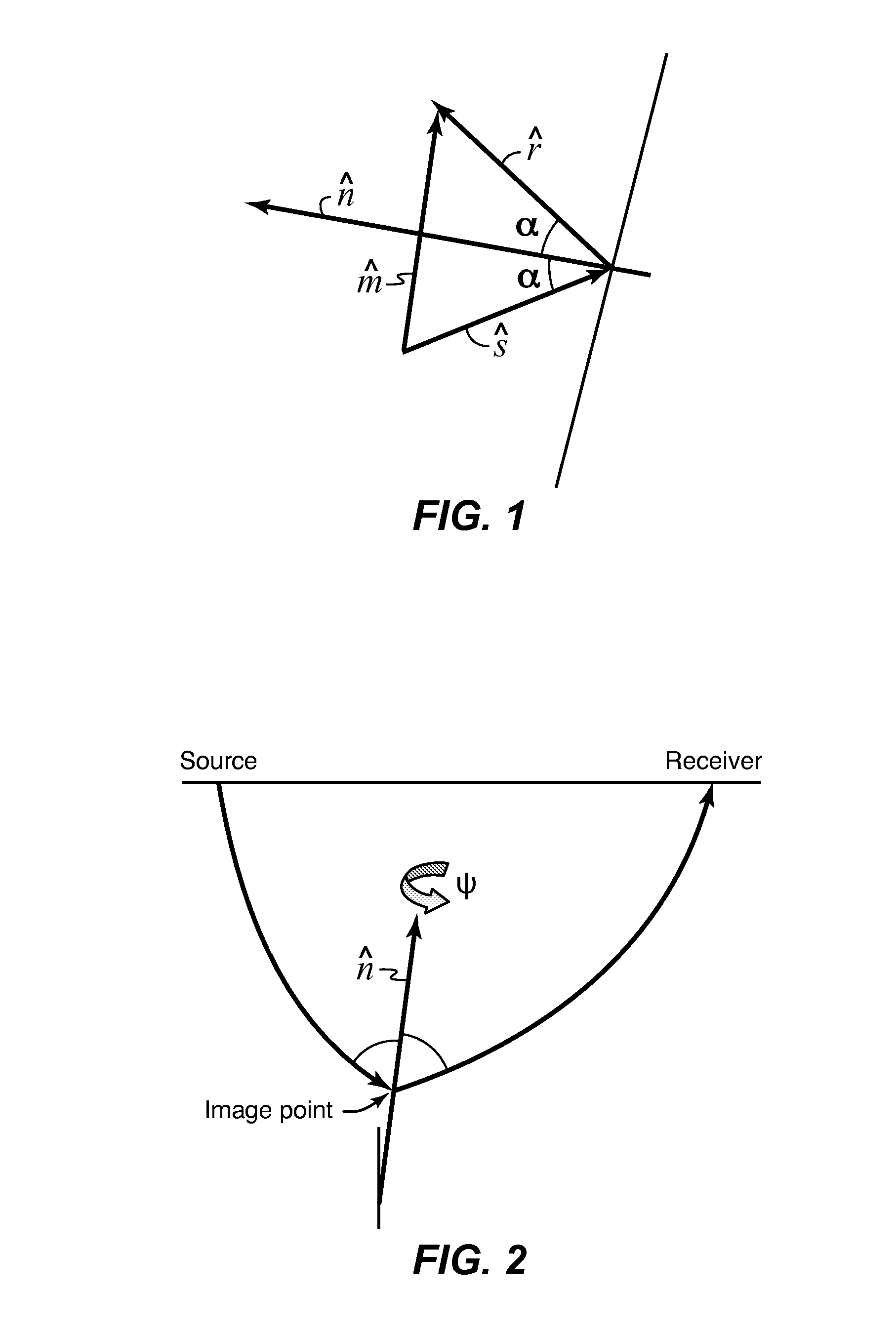
[0033]A teaching of the present invention is to continue the wave fields as described above, using either WEM or RTM, but to make the computationally inexpensive step of using multiple imaging conditions. For example for P-P imaging in an isotropic medium, the normal imaging condition in WEM and RTM is:

DM({right arrow over (x)})=∫dωps({right arrow over (x)},ω)pr*({right arrow over (x)},ω)  (3)

The convolution can of course be performed in either the frequency or time domain. Now, for example, in RTM the downward continuation can be computed in time using the first order equations, where p is pressure, v is local particle velocity, ρ is density, and λ is the bulk modulus:

[0034]ρ⁢∂v->∂t=-∇p(4)∂p∂t=-λ⁢⁢div(v->).(5)

[0035]This means that at each image point the pressure and local particle velocity are both available. Therefore one can also compute:

{right arrow over (s)}M({right arrow over (x)})=∫dω{right arrow over (v)}s({right arrow over (x)},ω)pr*({right arrow over (x)},ω)  (6)

This vect...


PUM


Abstract

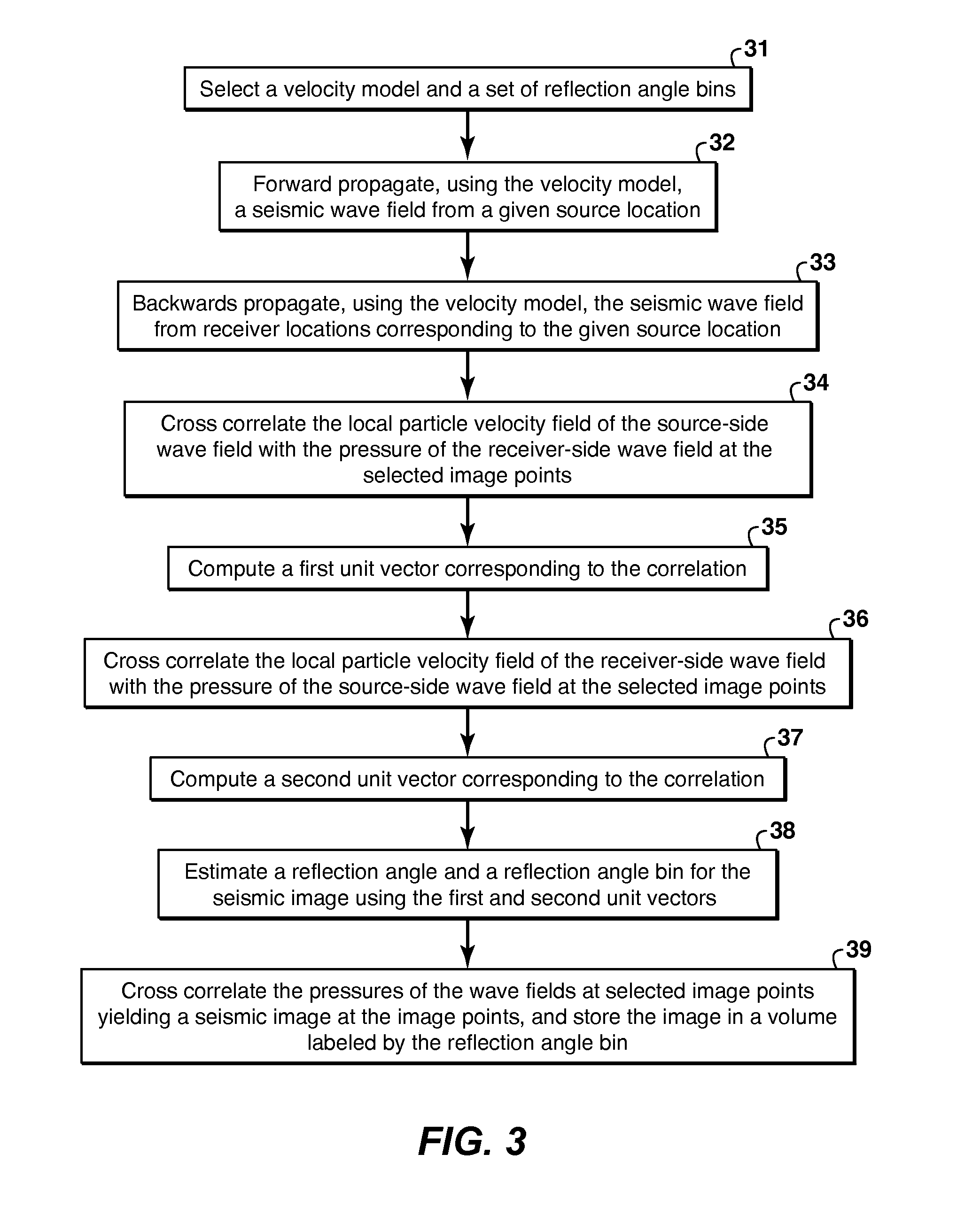
Method for efficient computation of wave equation migration angle gathers by using multiple imaging conditions. Common reflection angle or common azimuth gathers or gathers including both common reflection angles and common azimuth angles are produced as the data are migrated. In the course of either wave equation migration or reverse time migration, the pressures and particle motion velocities that need to be computed are sufficient to also compute the Poynting vector pointing in the direction of source-side (35) or receiver-side (37) wavefield propagation. From that, the reflection and azimuth angles can be computed (38). The seismic images can then be stored in the appropriate angle bins, from which common reflection angle or azimuth data volumes can be assembled (39).

Description

CROSS-REFERENCE TO RELATED APPLICATION[0001]This application is the National Stage of International Application No. PCT / US2011 / 033520, that published as WO 2011 / 152928, filed 22 Apr. 2011, which claims the benefit of U.S. Provisional Application No. 61 / 350,783 filed 2 Jun. 2010 and U.S. Provisional Application No, 61,472,955, filed 7 Apr. 2011, each of which is incorporated herein by reference, in its entirety, for all purpose. entitled EFFICIENT COMPUTATION OF WAVE EQUATION MIGRATION ANGLE GATHERS, both of which are incorporated by reference herein in their entirety.FIELD OF THE INVENTION[0002]This invention relates generally to the field of geophysical prospecting, and more particularly to the processing of seismic data. Specifically, the disclosure describes a method for migrating seismic data with efficient calculation at each image point of common reflection angle or common azimuth angle gathers or gathers including both common reflection angles and common azimuth angles.BACKGR...

Claims


Application Information

Patent Timeline
Patent Type & Authority Patents(United States)
IPC IPC(8): G06K9/00G01V1/28
CPCG01V1/282G01V2210/614G01V1/301G01V1/303G01V2210/512G01V2210/6222G01V2210/679G01V2210/632G01V1/325
Inventor WINBOW, GRAHAM A.DICKENS, THOMAS A.
Owner EXXONMOBIL UPSTREAM RES CO
Learn More