Adaptive timing recovery via generalized RAKE reception

a generalized rake and timing recovery technology, applied in the field of rake receivers, can solve the problems of orthogonality property loss, signal fading, and inability to precisely place the rake fingers at the peak of the pdp

Inactive Publication Date: 2015-02-24
TELEFON AB LM ERICSSON (PUBL)
View PDF20 Cites 10 Cited by
  • Summary
  • Abstract
  • Description
  • Claims
  • Application Information

AI Technical Summary

Problems solved by technology

The multiple time-shifted signal images combine at the receiver in an unpredictable manner resulting in signal fading.
As shown in FIG. 1, exact placement of the RAKE fingers at the peaks of the PDP is not always possible because the search grid does not always align with the peaks in the PDP.
If the grid is not aligned with the channel delay, then the orthogonality property is lost, and the contribution of other codes shows up as interference.
The impact of misalignment on performance can be dramatic at very high data rates when higher order modulation such as 16-QAM is employed, as this modulation is highly sensitive to self-interference.
Thus, when the path delay falls between two sampling intervals, the performance degradation can be severe.

Method used


Image

  • Adaptive timing recovery via generalized RAKE reception
  • Adaptive timing recovery via generalized RAKE reception
  • Adaptive timing recovery via generalized RAKE reception

Examples


Embodiment Construction

[0021]The present invention relates to a method and apparatus for determining finger placement in a RAKE receiver or chip equalization receiver. As used herein, the term RAKE receiver includes a generalized RAKE (G-RAKE) receiver as described in U.S. Pat. No. 6,363,104, which is incorporated herein by reference. The invention has application in single-input single-output (SISO) receivers, multiple-input, single-output (MISO) receivers, and multiple-input, multiple-output (MIMO) receivers.

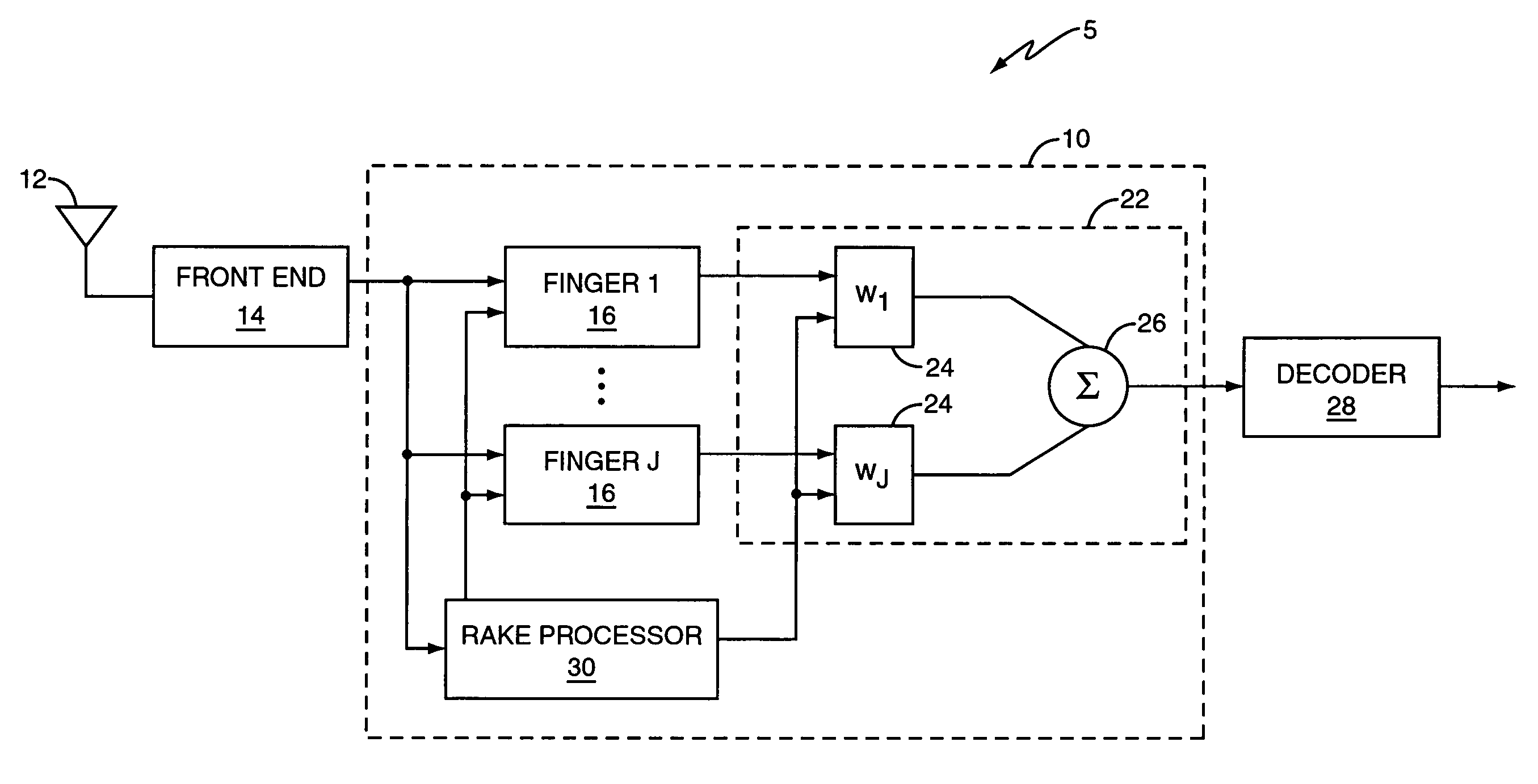
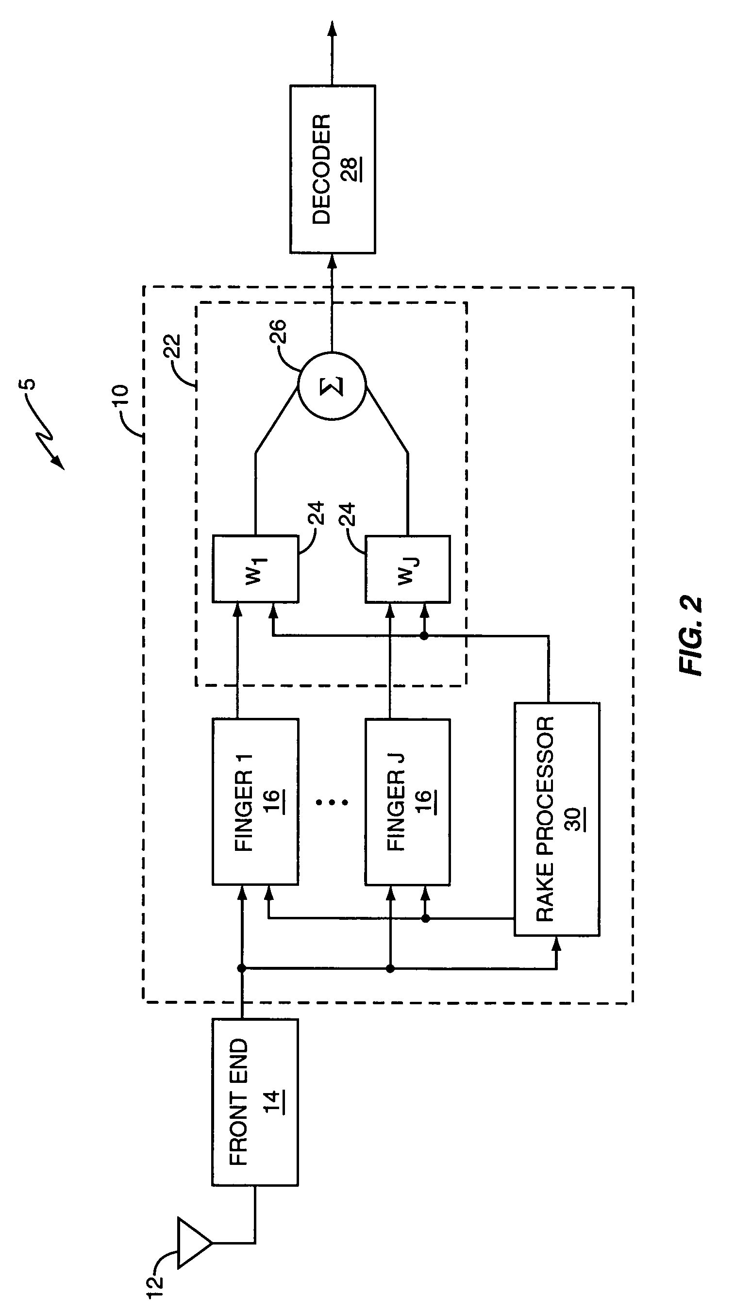
[0022]FIG. 2 illustrates a wireless receiver 5 including a RAKE receiver 10 according to one exemplary embodiment of the invention. The wireless receiver 5 comprises a receive antenna 12, a receiver front-end 14, a RAKE receiver 10, and a decoder 28. RAKE receiver 10 comprises a RAKE processor 30, a plurality of RAKE fingers 16 to detect respective signal images in a multi-path signal and a weighting network 22 to combine the outputs of the RAKE fingers 16 to generate a combined RAKE output signal. ...


PUM


Abstract

A method and apparatus for determining operating modes in a receiver is described herein. A delay searcher in the receiver detects a signal image in the received signal. When the receiver is a RAKE receiver, a plurality of RAKE fingers coherently combine time-shifted versions of the received signal at different delays. Alternatively, when the receiver is a chip equalization receiver, an FIR filter coherently pre-combines the signal images in the received signal. A processor determines delays. In particular, the processor generates a first signal quality metric for a single-delay receiver mode, and generates a second signal quality metric for a multi-delay receiver mode. Based on a comparison of the first and second signal quality metrics, the processor selects the single-delay or the multi-delay receiver mode for processing the signal image.

Description

[0001]This application claims priority benefit under 35 U.S.C. 119(e) from the U.S. provisional application Ser. No. 60 / 686,015, filed on 31 May 2005, and entitled “Adaptive Timing Recovery Via Generalized Rake Reception,” which is incorporated in its entirety by reference herein.BACKGROUND OF THE INVENTION[0002]The present invention relates generally to RAKE receivers for code division multiple access (CDMA) systems, and more particularly, to a method and apparatus for determining the finger placement of RAKE fingers in a RAKE receiver.[0003]In a wireless communication system, a transmitted signal may travel through multiple propagation paths so that the received signal is a composite of multiple time-shifted versions of the signal. The different time-shifted versions of the received signal, referred to herein as signal images, suffer from different phase and attenuation effects. The multiple time-shifted signal images combine at the receiver in an unpredictable manner resulting in...

Claims


Application Information

Patent Timeline
Patent Type & Authority Patents(United States)
IPC IPC(8): H04B1/10H04B1/7117H04B1/712
CPCH04B1/712H04B1/7117H04B2201/709727
Inventor CAIRNS, DOUGLAS A.BOTTOMLEY, GREGORY E.WANG, YI-PIN ERIC
Owner TELEFON AB LM ERICSSON (PUBL)
Why Eureka
Try Eureka