Peak detection method using blind source separation

a detection method and source separation technology, applied in the field of ultrawideband signal processing, can solve the problems of overcrowded frequency bands, low spectrum utilization by licensed wireless systems, and inability to cope with increasing data rates for a long tim

Inactive Publication Date: 2015-02-17
KING FAHD UNIVERSITY OF PETROLEUM AND MINERALS +1
View PDF4 Cites 17 Cited by
  • Summary
  • Abstract
  • Description
  • Claims
  • Application Information

AI Technical Summary

Benefits of technology

[0010]The peak detection method using blind source separation extracts true peaks from noisy peaks in a more robust way that does not require any a priori information. Information regarding true peak location is obtained by thresholding the output of a wavelet transform. The value of the threshold is dependent on noise variance. While noise variance is normally unknown, the method implements a blind source separation technique to calculate the noise variance. The blind source separation technique does not require information of the incoming signal or the channel noise, and hence is suitable for CR peak detection.
[0011]These and other features of the present invention will become readily apparent upon further review of the following specification and drawings.

Problems solved by technology

It has been observed that utilization of spectrum by licensed wireless systems, for instance TV broadcasting, is quite low.
Current static frequency allocation schemes cannot cope forever with increasing data rates.
Some frequency bands are overcrowded, and some are barely used.
When the incoming signal is noisy, these peaks are accompanied by noisy peaks.

Method used


Image

  • Peak detection method using blind source separation
  • Peak detection method using blind source separation
  • Peak detection method using blind source separation

Examples


Embodiment Construction

[0017]At the outset, it should be understood by one of ordinary skill in the art that embodiments of the present method can comprise software or firmware code executing on a computer, a microcontroller, a microprocessor, or a DSP processor; state machines implemented in application specific or programmable logic; or numerous other forms without departing from the spirit and scope of the method described herein. The present method can be provided as a computer program, which includes a non-transitory machine-readable medium having stored thereon instructions that can be used to program a computer (or other electronic devices) to perform a process according to the method. The machine-readable medium can include, but is not limited to, floppy diskettes, optical disks, CD-ROMs, and magneto-optical disks, ROMs, RAMs, EPROMs, EEPROMs, magnetic or optical cards, flash memory, or other type of media or machine-readable medium suitable for storing electronic instructions.

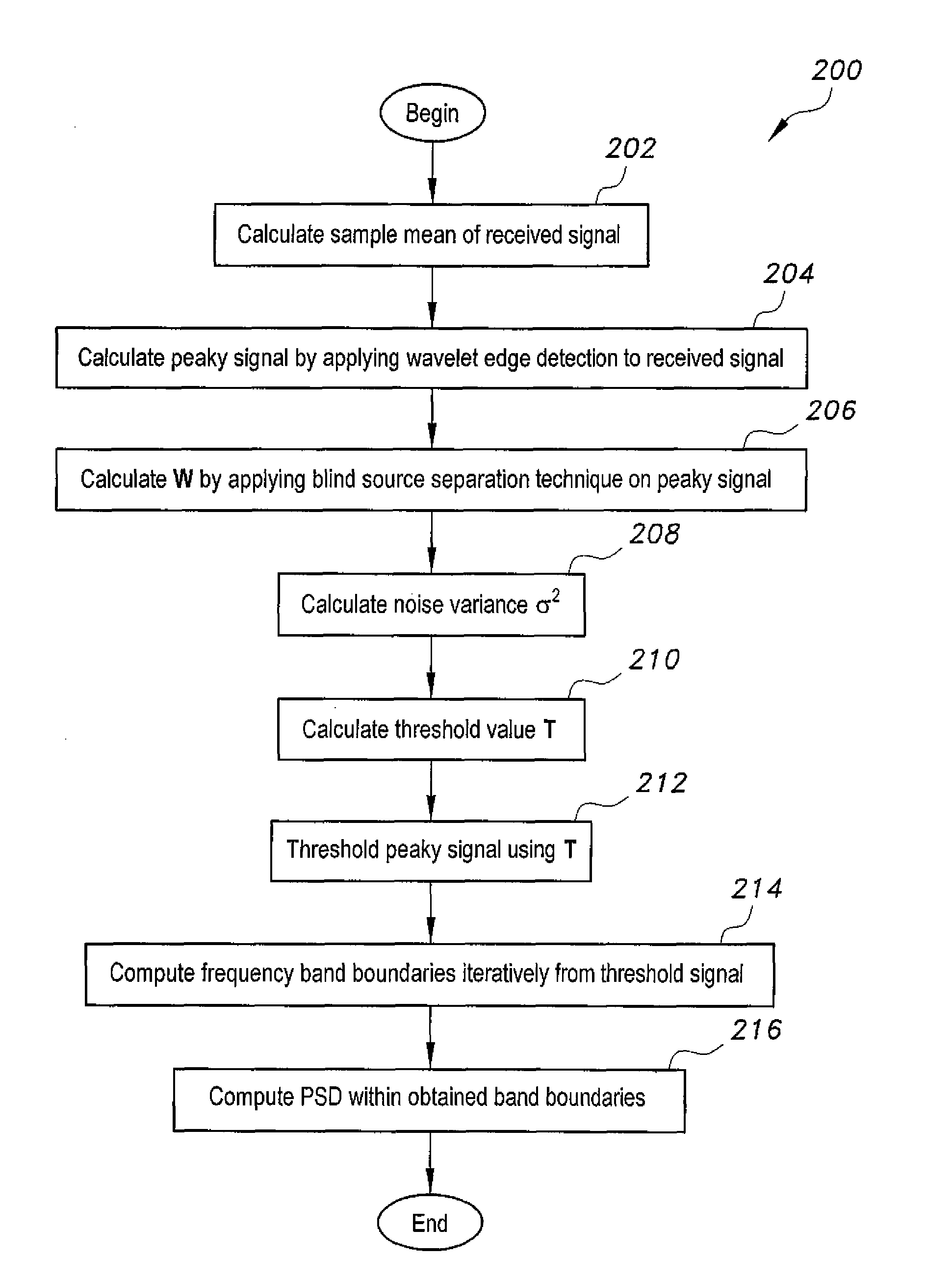
[0018]The peak detec...


PUM


Abstract

The peak detection method using blind source separation extracts true peaks from noisy peaks in a more robust way that does not require any a priori information. Information regarding true peak location is obtained by thresholding the output of a wavelet transform. The value of the threshold is dependent on noise variance. While noise variance is normally unknown, the present method implements a blind source separation technique to calculate the noise variance. The blind source separation technique does not require information of the incoming signal or the channel noise, and hence is suitable for CR (cognitive radio) peak detection.

Description

BACKGROUND OF THE INVENTION[0001]1. Field of the Invention[0002]The present invention relates to ultra-wideband signal processing, and particularly to a peak detection method using blind source separation.[0003]2. Description of the Related Art[0004]Efficient utilization of radio spectrum has gained recent attention. It has been observed that utilization of spectrum by licensed wireless systems, for instance TV broadcasting, is quite low. Transition from voice only data services to multimedia services requires high data rates. Current static frequency allocation schemes cannot cope forever with increasing data rates. Some frequency bands are overcrowded, and some are barely used. A spectrum occupancy measurement project concluded that the average spectrum occupancy over multiple locations is 5.2%, with a maximum of 13.1%.[0005]Cognitive radio (CR) seems a tempting solution to resolve the perceived bandwidth scarcity versus under-utilization dilemma. CR uses opportunistic usage of ba...

Claims


Application Information

Patent Timeline
Patent Type & Authority Patents(United States)
IPC IPC(8): H04B15/00H04B17/00H03F1/26H04B1/10
CPCH04B1/1027H04B2001/1045H04W16/14H04L27/0004H04L27/0006H04B1/719H04B2201/692G06F2218/06G06F2218/10G06F2218/22
Inventor SALEEM, ZAHIDAL-GHADHBAN, SAMIRAL-NAFFOURI, TAREQ Y.
Owner KING FAHD UNIVERSITY OF PETROLEUM AND MINERALS
Why Eureka
Try Eureka