
Method of producing isotopes in power nuclear reactors

Active Publication Date: 2015-02-10
NORDION (CANADA) INC
View PDF88 Cites 4 Cited by
  • Summary
  • Abstract
  • Description
  • Claims
  • Application Information

AI Technical Summary

Problems solved by technology

These research reactors are not intended nor designed for commercial power generation, since they are being designed for power levels of about 10 MWt.

Method used


Image

  • Method of producing isotopes in power nuclear reactors
  • Method of producing isotopes in power nuclear reactors
  • Method of producing isotopes in power nuclear reactors

Examples


Embodiment Construction

[0017]As to be described in further detail below, the exemplary embodiments may be directed to using power light water reactors designed for commercial power generation to produce medical and industrial isotopes, in addition to generating thermal and electrical power for residential, commercial and / or industrial use. Unlike research reactors dedicated only to the production of radioisotopes, these light water power reactors may be existing boiling water reactors (BWRs) and / or pressurized water reactors (PWRs) that are configured to generate at least 100 megawatts thermal (MWt) and in example on the order of several hundred or thousand MWt. These power LWRs generally have a bundle average enrichment of less than 10%.

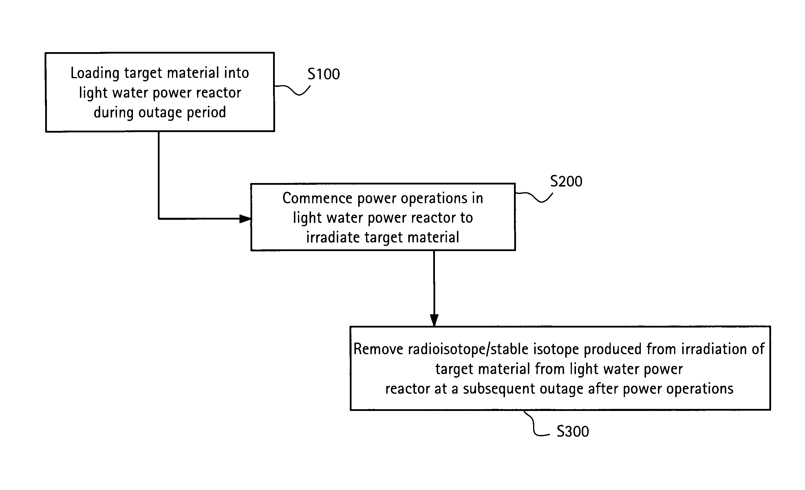
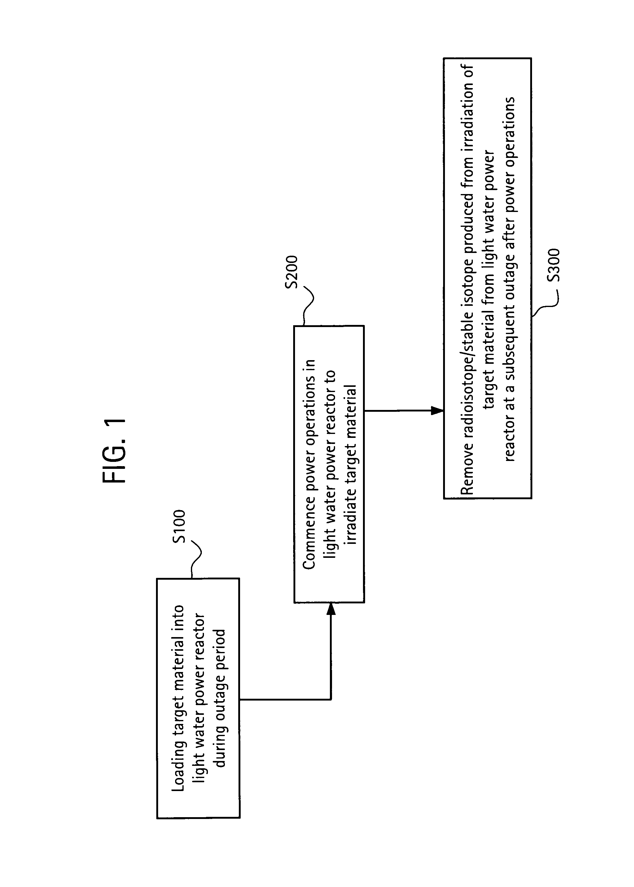
[0018]FIG. 1 is a flow chart illustrating a method of producing isotopes in a light water power reactor, in accordance with an exemplary embodiment of the invention. Referring to FIG. 1, isotope target material may be loaded into a light water power reactor during a plann...


PUM


Abstract

In a method of producing isotopes in a light water power reactor, one or more targets within the reactor may be irradiated under a neutron flux to produce one or more isotopes. The targets may be assembled into one or more fuel bundles that are to be loaded in a core of the reactor at a given outage. Power operations in the reactor irradiate the fuel bundles so as to generate desired isotopes, such as one or more radioisotopes at a desired specific activity or stable isotopes at a desired concentration.

Description

BACKGROUND OF THE INVENTION[0001]1. Field of the Invention[0002]This invention relates generally to isotope production in light water power reactors.[0003]2. Description of the Related Art[0004]A wide variety of radioactive isotopes are used for medical, industrial, research, and commercial applications. In general, radioisotopes may be produced by irradiating target isotope materials with nuclear particles. The target atoms either transmute directly into the desired isotope, or a radioisotope is produced through a chain of absorption and decay that subsequently generates the desired radioactive product.[0005]The latter is the case, for example, in the production of the important medical imaging isotope Technetium-99m, which represents about 90% of the isotopes used in today's nuclear medicine. Tc-99m produces high-energy gamma rays, which makes detection easy, and its short half-life of 6 hours minimizes the radiation dose delivered to the patient. Nuclear medical imaging is unique...

Claims


Application Information

Patent Timeline
Patent Type & Authority Patents(United States)
IPC IPC(8): G21G1/00G01S13/933G21G1/02
CPCG21G1/02Y02E30/30G21C1/303G01S13/933
Inventor FAWCETT, RUSSELL MORGANGONZALES, RANDY PETERHIGGINS, RUSSELL PATRICKJAMES, ROBERT BRYANTKIERNAN, MICHAEL THOMASRUSSELL, II, WILLIAM EARLSHELTON, STEVEN BRUCESMITH, DAVID GREYSTACHOWSKI, RUSSELL EDWARDTROSMAN, LUKAS
Owner NORDION (CANADA) INC
Learn More