Windbreak structure for saddle type vehicle

a technology of windbreak structure and saddle type, which is applied in the direction of roof, cycle equipment, cycle, etc., can solve the problems of insufficient air to a central portion in the forward and backward direction of the vehicle positioned behind the leg shield

Active Publication Date: 2015-02-10
HONDA MOTOR CO LTD
View PDF3 Cites 7 Cited by
  • Summary
  • Abstract
  • Description
  • Claims
  • Application Information

AI Technical Summary

Benefits of technology

[0007]The present invention has been made in view of the situation described above, and it is an object of an embodiment of the present invention to provide a windbreak structure for a saddle type vehicle by which a windshield effect behind a leg shield can be raised.
[0008]In order to solve the problem described above, according to an embodiment of the present invention, there is provided a windbreak structure for a saddle type vehicle that has a leg shield (601) for covering the feet of an occupant from the front, wherein an exhaust port (641) for letting a flow of air from the front of a vehicle body to flow rearwardly is provided at a side end portion of the leg shield (601). In addition, an exhaust air guide portion (602A1) that extends rearwardly is provided on the inner side in a vehicle widthwise direction of the exhaust port (641). With this configuration, the exhaust port for letting a flow of air from the front of the vehicle body to flow rearwardly is provided at the side end portion of the leg shield, and the exhaust air guide portion that extends rearwardly is provided on the inner side in the vehicle widthwise direction of the exhaust port. Therefore, a flow of air to the rear from the exhaust port can be guided along the exhaust air guide portion to smoothly flow rearwardly. Consequently, the area wherein a catch up of a flow of air can be prevented can be expanded rearwardly, and the windshield effect behind the leg shield can be enhanced.

Problems solved by technology

Therefore, the amount of air to a central portion in the forward and backward direction of the vehicle positioned behind the leg shield is insufficient, and there is the possibility that the area wherein a catch-up of a flow of air can be prevented behind the leg shield may be narrowed.

Method used


Image

  • Windbreak structure for saddle type vehicle
  • Windbreak structure for saddle type vehicle
  • Windbreak structure for saddle type vehicle

Examples


Embodiment Construction

[0035]In the following, an embodiment of the present invention is described with reference to the drawings. It is to be noted that, unless otherwise specified, expressions of directions such as forward and backward, leftward and rightward, and upward and downward directions are the same as the directions with reference to the vehicle body. Further, reference character FR in the figures indicates the forward direction of the vehicle body, reference character UP indicates the upward direction of the vehicle body, and reference character LE indicates the leftward direction of the vehicle body.

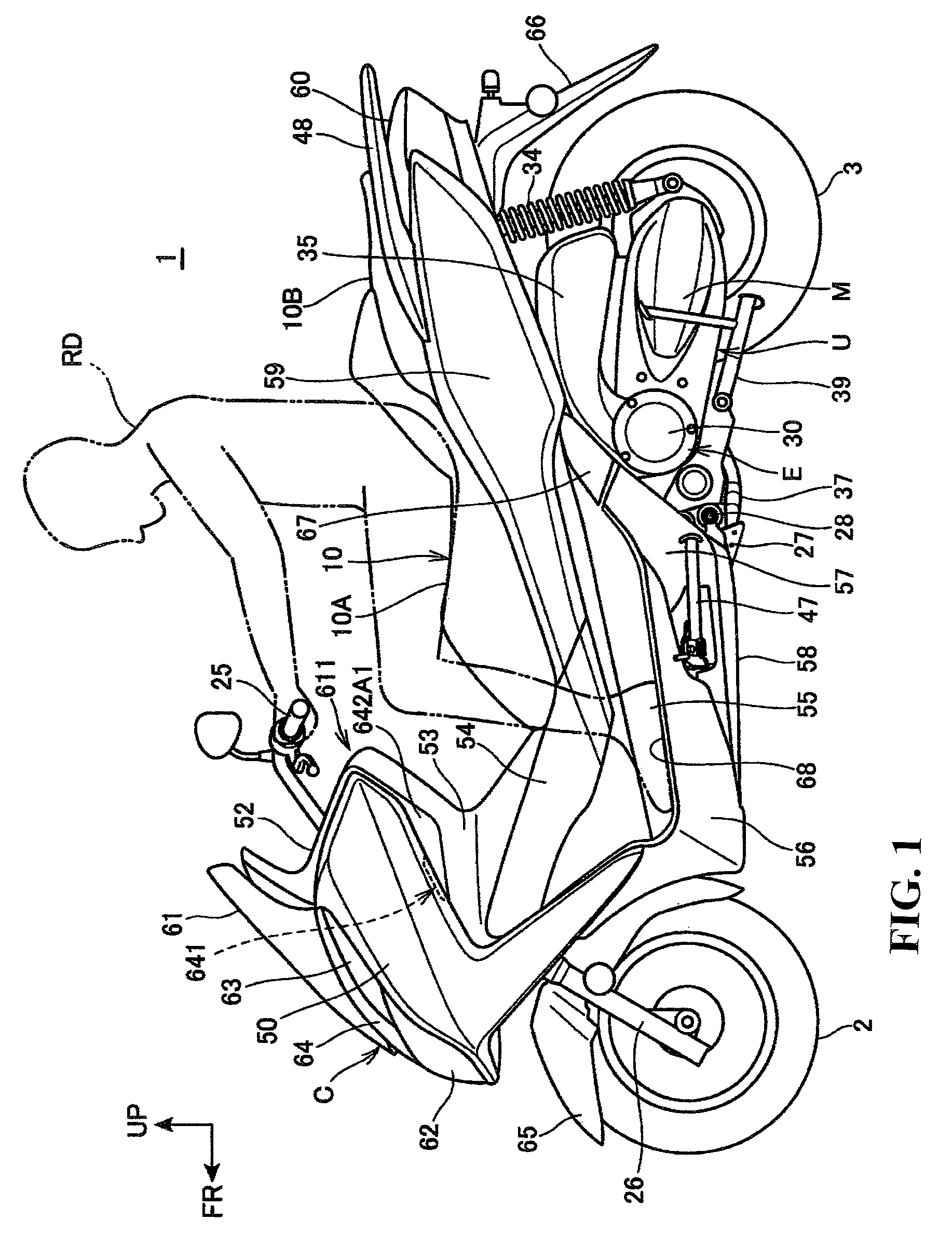
[0036]FIG. 1 is a left side elevational view of a motorcycle according to an embodiment of the present invention.

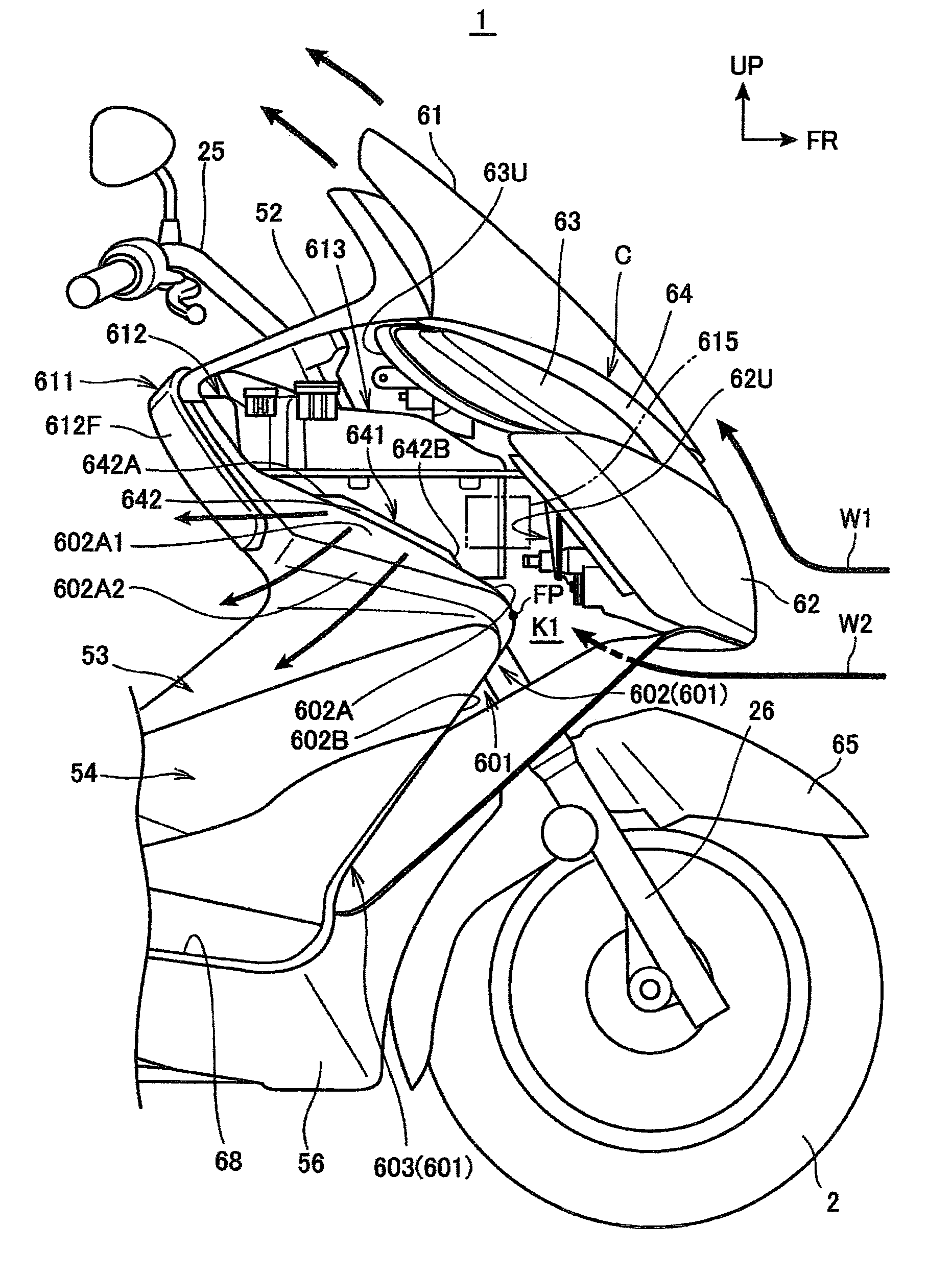
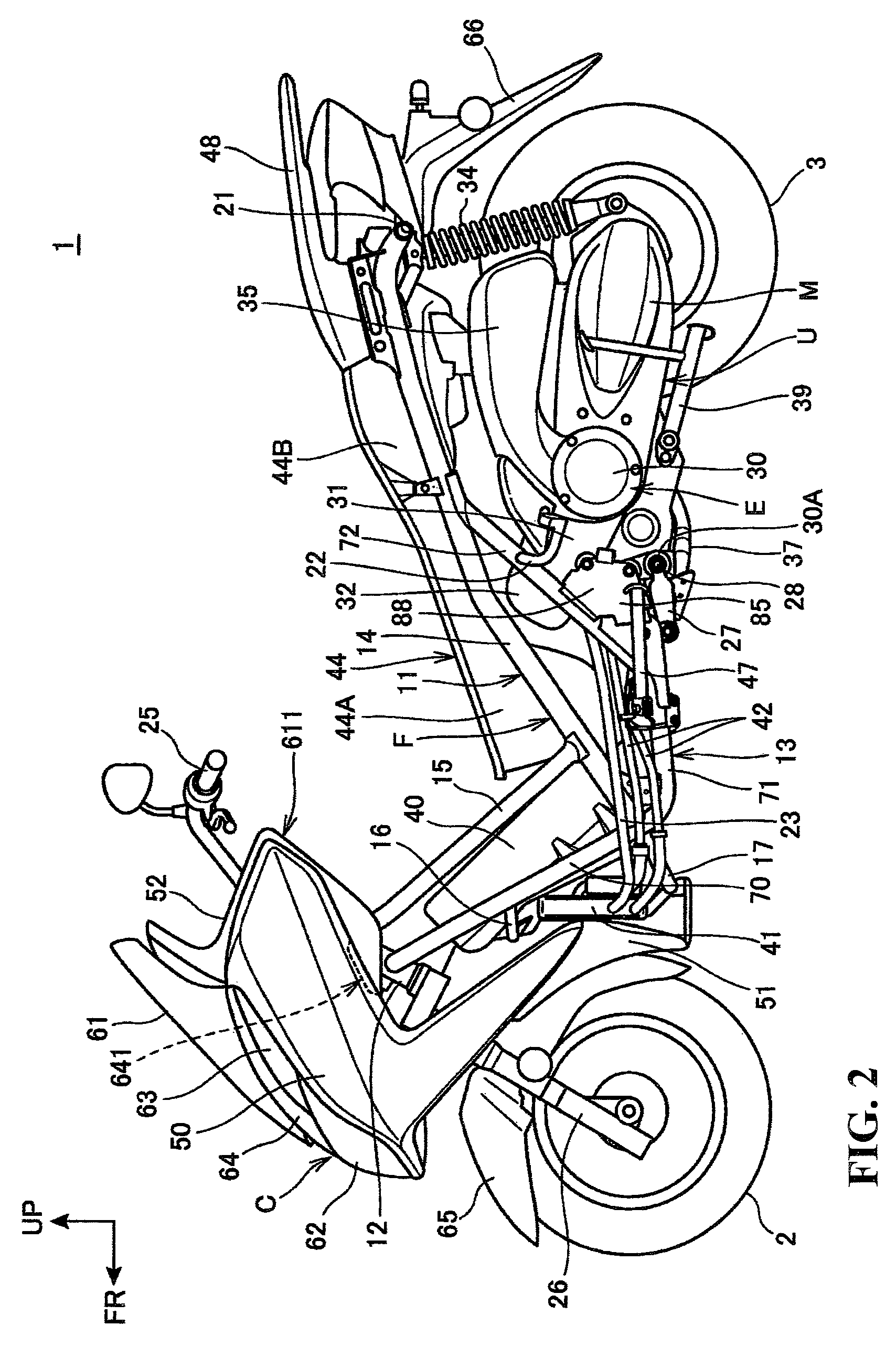
[0037]The motorcycle (saddle type vehicle) 1 is a scooter type vehicle having a step floor 68 of the low floor type on that an occupant RD (rider) seated on a seat 10 is to place his / her feet. The motorcycle 1 has a front wheel 2 at a front portion of a vehicle body frame F (FIG. 2), an...


PUM


Abstract

A windbreak structure for a saddle type vehicle to provide an increase in the windshield effect behind a leg shield. Exhaust ports for letting a flow of air from the front of a vehicle body rearwardly are provided at a side end portion of a leg shield. Further, sideward covering portions are provided that serve as exhaust air guide portions that extend rearwardly on the inner side in a vehicle widthwise direction of the exhaust port.

Description

CROSS-REFERENCE TO RELATED APPLICATIONS[0001]The present application claims priority under 35 USC 119 to Japanese Patent Application No. 2012-064849 filed Mar. 22, 2012 the entire contents of that are hereby incorporated by reference.BACKGROUND OF THE INVENTION[0002]1. Field of the Invention[0003]The present invention relates to a windbreak structure for a saddle type vehicle that has a leg shield for covering the feet of an occupant from the front.[0004]2. Description of Background Art[0005]Some saddle type vehicles such as motorcycles have a leg shield that covers the feet of an occupant from the front. A vehicle of the type described has been proposed wherein a flow of air from the front of the vehicle body is introduced into a duct through an inlet port perforated in the front face of a front cover and is blown out to side end portions of the leg shield from the duct. See, for example, Japanese Patent Laid-Open No. Hei 10-203454. By blowing out a flow of air to the side end port...

Claims


Application Information

Patent Timeline
Patent Type & Authority Patents(United States)
IPC IPC(8): B62J17/06B62J17/04
CPCB62J17/06B62J17/04B62K2202/00
Inventor YOKOUCHI, KOHEISHIMOJI, TOMOTAKESASAZAWA, HIROYUKI
Owner HONDA MOTOR CO LTD
Why Eureka
Try Eureka