
Liquid jet head and liquid jet apparatus

a liquid jet and apparatus technology, applied in the direction of printing and inking apparatus, etc., can solve the problems of affecting the ejection performance (printing stability), affecting the image quality of recording paper, and the volume of ink droplets also decreasing or increasing, so as to achieve stable liquid ejection performance and print stability, and high versatility. , the effect of sufficient pressure buffering

Active Publication Date: 2015-02-03
SII PRINTEK
View PDF10 Cites 0 Cited by
  • Summary
  • Abstract
  • Description
  • Claims
  • Application Information

AI Technical Summary

Benefits of technology

[0011]The present invention has been made in view of the above circumstances, and is directed to provide a liquid jet head that can obtain a sufficient pressure buffering effect and has high versatility, and a liquid jet apparatus provided with the same.
[0032]According to the present invention, it is possible to obtain a sufficient pressure buffering effect and provide the liquid jet head and the liquid jet apparatus having high versatility.

Problems solved by technology

However, in the above ink jet head, for example, pressure fluctuation inside a channel which occurs when ejecting ink is disadvantageously transmitted as a pressure wave to the common ink chamber and the other channels through the common ink chamber, which affects the ejection performance (printing stability).
At the same time, the volume of ink droplets also decreases or increases, which affects the image quality on a recording paper.
In addition, the pressure fluctuation becomes large when the ejection amount per unit time increases or the size of liquid droplets increases.
Therefore, when such a configuration is applied to the side shoot type ink jet head, it is difficult to effectively suppress pressure fluctuation that occurs inside the channels.

Method used


Image

  • Liquid jet head and liquid jet apparatus
  • Liquid jet head and liquid jet apparatus
  • Liquid jet head and liquid jet apparatus

Examples


Embodiment Construction

[0043]Hereinbelow, an embodiment of the present invention will be described with reference to the accompanying drawings. In the following embodiment, an ink jet printer (hereinbelow, just referred to as the printer) that uses ink (liquid) to perform recording on a recording paper will be described as an example of a liquid jet apparatus that is provided with a liquid jet head of the present invention.

[0044][Printer]

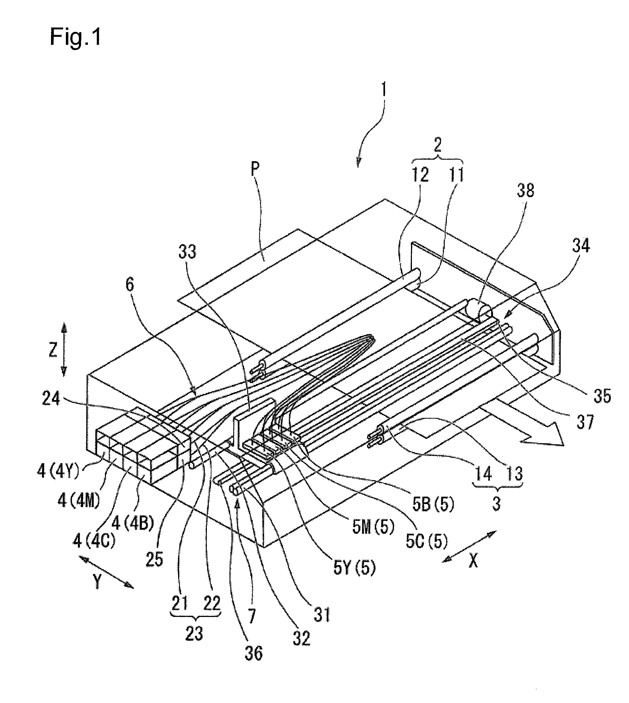
[0045]FIG. 1 is a schematic configuration diagram of a printer 1.

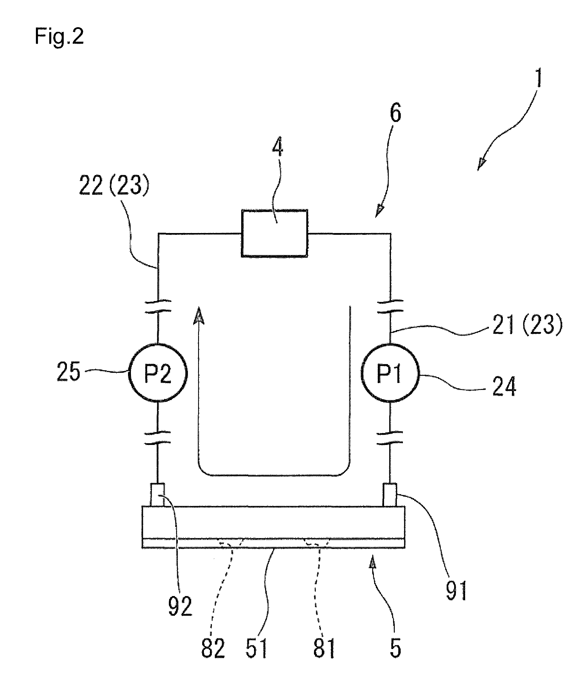
[0046]As illustrated in FIG. 1, the printer 1 of the present embodiment is provided with a pair of conveyance units 2 and 3 which conveys a recording paper (recording medium) P such as paper, an ink tank (liquid tank) 4 which stores ink therein, an ink jet head (liquid jet head) 5 which ejects ink in the form of liquid droplets onto the recording paper P, an ink circulation unit (circulation unit) 6 which circulates ink between the ink tank 4 and the ink jet head 5, and a scanning unit (conveyance unit) 7 wh...


PUM


Abstract

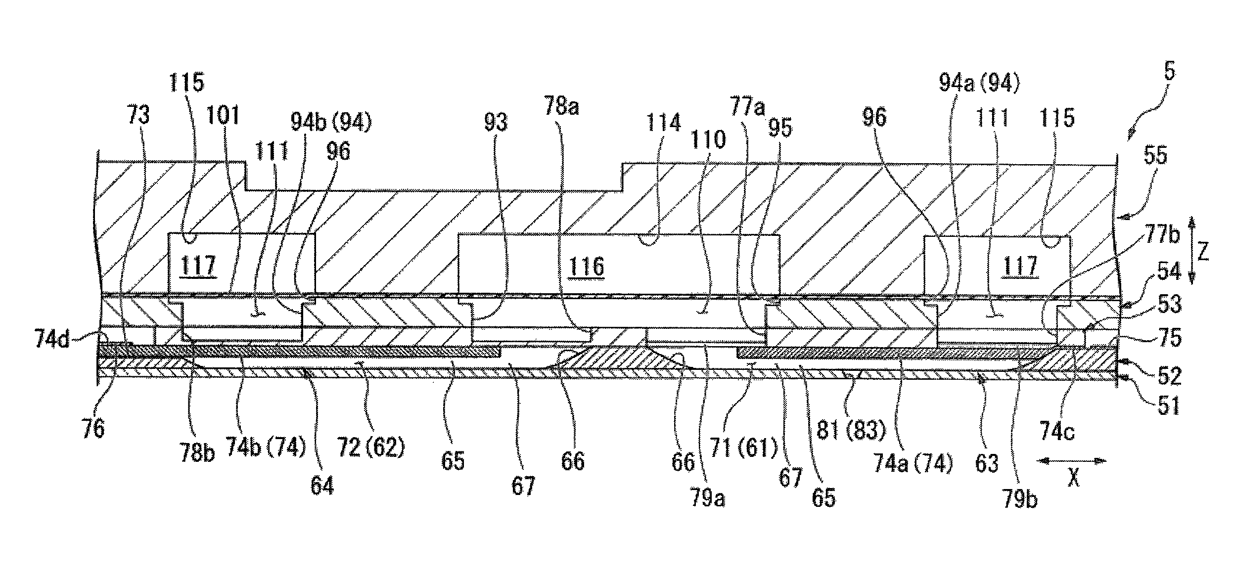
A liquid jet head is provided with: a nozzle plate which includes a nozzle array having a plurality of nozzle holes arranged side by side along a Y direction; an actuator plate which is laminated on the nozzle plate and includes a channel group having a plurality of first channels communicating with the nozzle holes, the first channels being arranged in parallel at intervals along the Y direction; and an inlet ink chamber and an outlet ink chamber both communicating with the first channels on opposite ends in an extending direction of the first channels. A film member which can be warp-deformed along with pressure fluctuation inside the inlet ink chamber and the outlet ink chamber is arranged as a part of inner surfaces of each of the inlet ink chamber and the outlet ink chamber.

Description

BACKGROUND[0001]1. Technical Field[0002]The present invention relates to a liquid jet head and a liquid jet apparatus.[0003]2. Related Art[0004]Conventionally, there has been used an ink jet printer (liquid jet apparatus) that is provided with an ink jet head (liquid jet head) as an apparatus that ejects ink in the form of liquid droplets onto a recording paper (recording medium) to record an image or a character thereon.[0005]Generally, an ink jet head is provided with a nozzle plate which has a nozzle array including a plurality of nozzle holes, an actuator plate which has a plurality of channels communicating with the respective nozzle holes, and a cover plate which has a common ink chamber communicating with the channels. In such a configuration, a channel is caused to contract to increase the pressure inside thereof, thereby ejecting ink inside the channel from the corresponding nozzle hole to allow the ink to adhere on a recording paper.[0006]However, in the above ink jet head...

Claims


Application Information

Patent Timeline
Patent Type & Authority Patents(United States)
IPC IPC(8): B41J2/04B41J2/045
CPCB41J2/045B41J2/14209B41J2202/12B41J2002/14419B41J2202/10
Inventor DOMAE, YOSHINORI
Owner SII PRINTEK
Learn More