Obstetric forceps

a technology of forceps and ovaries, applied in the field of ovaries, can solve the problems of reducing the safety of delivery devices, so as to reduce the risk of vaginal damage, increase the grip on the head of the baby, and increase the effect of grip

Inactive Publication Date: 2015-01-27
OBOH ALEX +3
View PDF37 Cites 0 Cited by
  • Summary
  • Abstract
  • Description
  • Claims
  • Application Information

AI Technical Summary

Benefits of technology

The force indicator helps users safely use forceps by providing a real-time indication of the force being applied. It also includes a smoothly curved surface that reduces the risk of harm to the vaginal wall by having a continuous curve without any edge discontinuities.

Problems solved by technology

For example, the user's experience, levels of tiredness and physical size and strength may all affect how much force is applied to the baby while trying to deliver the baby using forceps.
If too much force is applied then the baby or mother or both can be harmed in a variety of ways.
Alternatively, if a user does not apply enough force, then the use of forceps can be abandoned prematurely in favour of other potentially more invasive or harmful delivery techniques.
Such systems are complex to use, set up and install, costly and add significantly to the equipment present in a delivery room.
Such forceps provide limited feedback to a user as to how much force is being applied to a baby in use.
Further, irrespective of the amount of force applied, it is also possible for forceps to harm the mother and / or baby.

Method used


Image

  • Obstetric forceps
  • Obstetric forceps
  • Obstetric forceps

Examples


Embodiment Construction

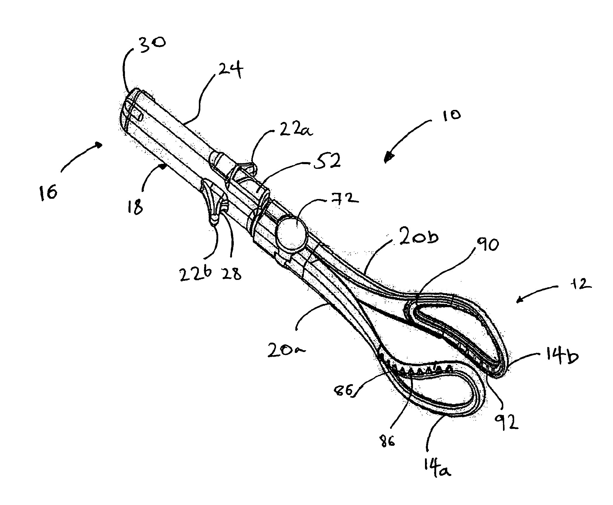
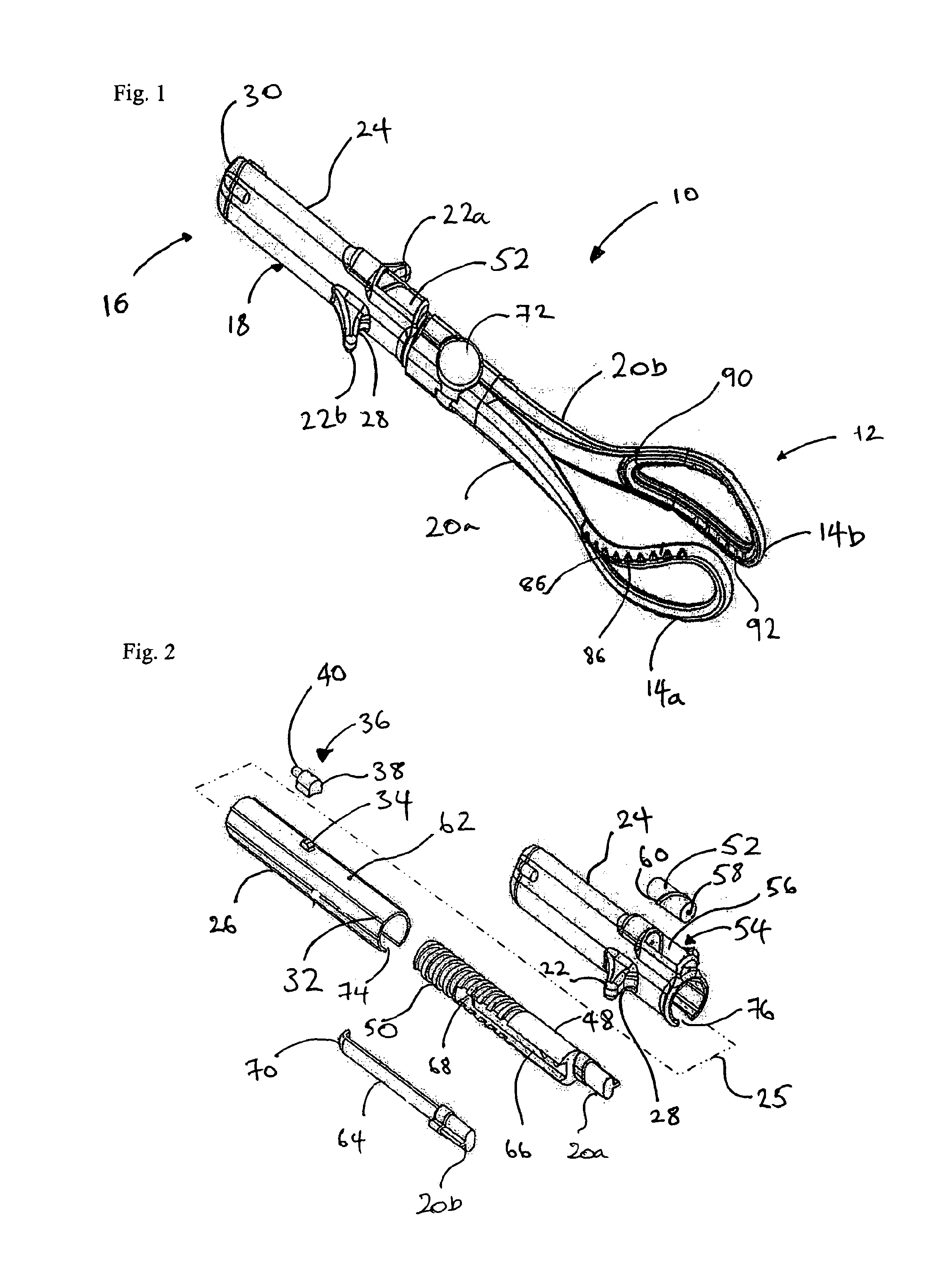
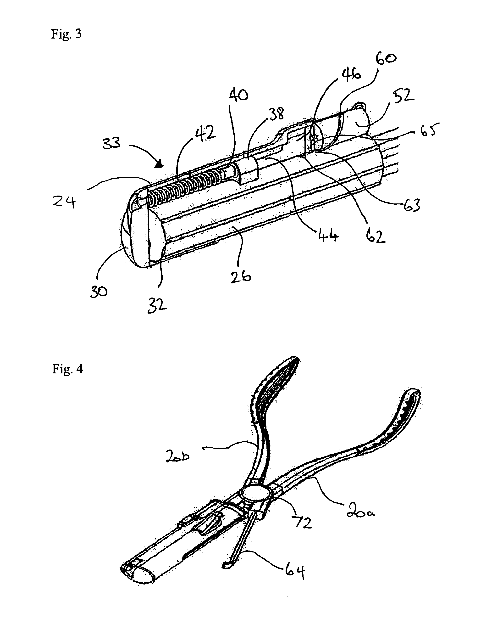
[0053]In the Figures, similar parts share common reference signs unless indicated otherwise. FIGS. 1 to 9 show a first embodiment of the obstetric forceps of the invention and FIGS. 10 to 13 show a second embodiment of the obstetric forceps of the invention. The second embodiment is substantially similar to the first embodiment, but with some structural differences, and operates and is used in a similar manner to the first embodiment. The reference signs used for the second embodiment are similarly numbered to the reference signs for the first embodiment but prefixed with one.

[0054]With reference to FIG. 1 there is shown a pair of obstetric forceps 10 according to the invention. The obstetric forceps 10 have first and second blades 14a, 14b toward a first or distal end 12 and a handle 18 toward second or proximal end 16. The first and second blades 14a, 14b are connected to the handle 18 via respective first 20a and second 20b shanks. First and second finger grips 22a, 22b extend fr...


PUM


Abstract

A pair of obstetric forceps is described. The forceps comprise a pair of blades for holding the head of a baby and a handle having at least one part by which a user can apply a pulling force on the head of the baby in use. A mechanically operated force indicator is connected to the at least one part of the handle and is operable to provide a visual indication of the amount of pulling force being applied to the head of the baby when a user applies a pulling force on the head of the baby in use. A mechanically operated disabling device is operable to at least partially disable the obstetric forceps when a maximum pulling force has been exceeded. The blades can each have a superior rim and inferior rim wherein the greatest separation between the superior rims is greater than the greatest separation between the inferior rims when the obstetric forceps are in a closed configuration so that the blades adopt the form of an at least partially bowl shape.

Description

BACKGROUND[0001]1. Field of the Invention[0002]The present invention relates to obstetric forceps. In particular, the invention relates to obstetric forceps which provide feed back to a user when excessive force is applied to a baby's head. The invention also relates to obstetric forceps with improved blades.[0003]2. Description of Related Art[0004]Obstetric forceps for assisting in the birth of a baby are well known. In practice, the amount of pulling force which is applied to a baby during use of the forceps depends on a number of factors. Some of these factors relate to the mother and baby and other relate to the user of the forceps. For example, the user's experience, levels of tiredness and physical size and strength may all affect how much force is applied to the baby while trying to deliver the baby using forceps. If too much force is applied then the baby or mother or both can be harmed in a variety of ways. Alternatively, if a user does not apply enough force, then the use ...

Claims


Application Information

Patent Timeline
Patent Type & Authority Patents(United States)
IPC IPC(8): A61B17/42A61B17/44A61B19/00
CPCA61B17/44A61B2017/445A61B2017/447A61B2019/444A61B2019/464A61B90/92A61B2090/064
Inventor OBOH, ALEXFLOOD, TIMOTHYHALL, RICHARDTHORNING, PAUL
Owner OBOH ALEX
Why Eureka
Try Eureka