
Method for controlling a rolling or coasting function of a vehicle

a technology for rolling or coasting and vehicles, applied in mechanical devices, transportation and packaging, road transportation, etc., can solve the problems of not always correctly interpreting the driving situation, relatively complex and error-prone, and unnecessary shifting into neutral or interruption of the flow of power

Inactive Publication Date: 2015-01-27
ZF FRIEDRICHSHAFEN AG
View PDF28 Cites 4 Cited by
  • Summary
  • Abstract
  • Description
  • Claims
  • Application Information

AI Technical Summary

Benefits of technology

The invention provides a method for controlling a vehicle's rolling or coasting function, which can be effectively and reliably used during suitable driving situations. The method recognizes downhill gradient tapers as a particularly suitable roadway topography for rolling or coasting and activates the rolling or coasting function to achieve a high savings effect. It also recognizes unsuitable downhill gradient tapers to prevent unnecessary shifting or interruption of power flow, improving the efficiency of driving operation. The coordination of the rolling or coasting function and a Tempomat / Bremsomat system can be controlled by existing transmission controls, without changing the software in the controllers for these systems. Additionally, the method includes a provision to temporarily increase the amount of fuel injected in the engine to reduce the thrust-related transmission force of the shifting element of the gear, if the force of the actuator is insufficient to overcome the friction in the shifting elements.

Problems solved by technology

However, it has been shown that the known methods for identifying suitable driving situations for rolling or coasting mode do not always correctly interpret the driving situation, or are relatively complex and error-prone due to a somewhat unfiltered consideration of topographical conditions of the roadway, and / or an insufficient consideration of the current driving status.
This frequently results in unnecessary shifting into neutral or interruption of the flow of power in the drive train that are undesirable depending on the situation and possibly counterproductive.
A disadvantage is that although unnecessary neutral shifting is sometimes prevented close to the situation, there is no anticipatory activation of the rolling or coasting function in particularly suitable situations or anticipatory deactivation that sufficiently considers the respective topographical conditions.
In addition, the combination of rolling or coasting operation with Tempomat and Bremsomat systems, which are increasingly found in modern vehicles, is not provided.
However, it is somewhat limited to an immobile or nearly immobile vehicle and hence cannot be easily transferred in driving mode to so-called rolling or coasting on flat areas or a downhill gradient.
This is also not easily applicable to downhill travel with a subsequent transition to a flat area.
The disadvantage thereof is that an anticipatory evaluation of the rolling mode is not provided, and therefore unfavorable neutral shiftings can be triggered.
In particular, the topographical driving situation is not taken into sufficient consideration.
The rotational speed of the drive motor and possibly of an active constant braking device is thereby reduced which could cause the motor vehicle to accelerate due to the lower engine drag torque and possibly lower retarder braking torque, thereby causing the traction mode to start comparatively later.
In addition, various criteria can be provided such as the actuation of the service brake, excessive vehicle acceleration, an excessively steep downhill gradient, a particularly heavy load, the operation of an auxiliary brake at its load limit, exceeding a target speed or falling below a safe separation distance regulated by an active Tempomat or Bremsomat that, for reasons of safety, lead to the blocking of thrust upshifting.
However, the efficiency of a rolling or coasting function tends not to be realized in the known method.

Method used


Image

  • Method for controlling a rolling or coasting function of a vehicle
  • Method for controlling a rolling or coasting function of a vehicle

Examples


Embodiment Construction

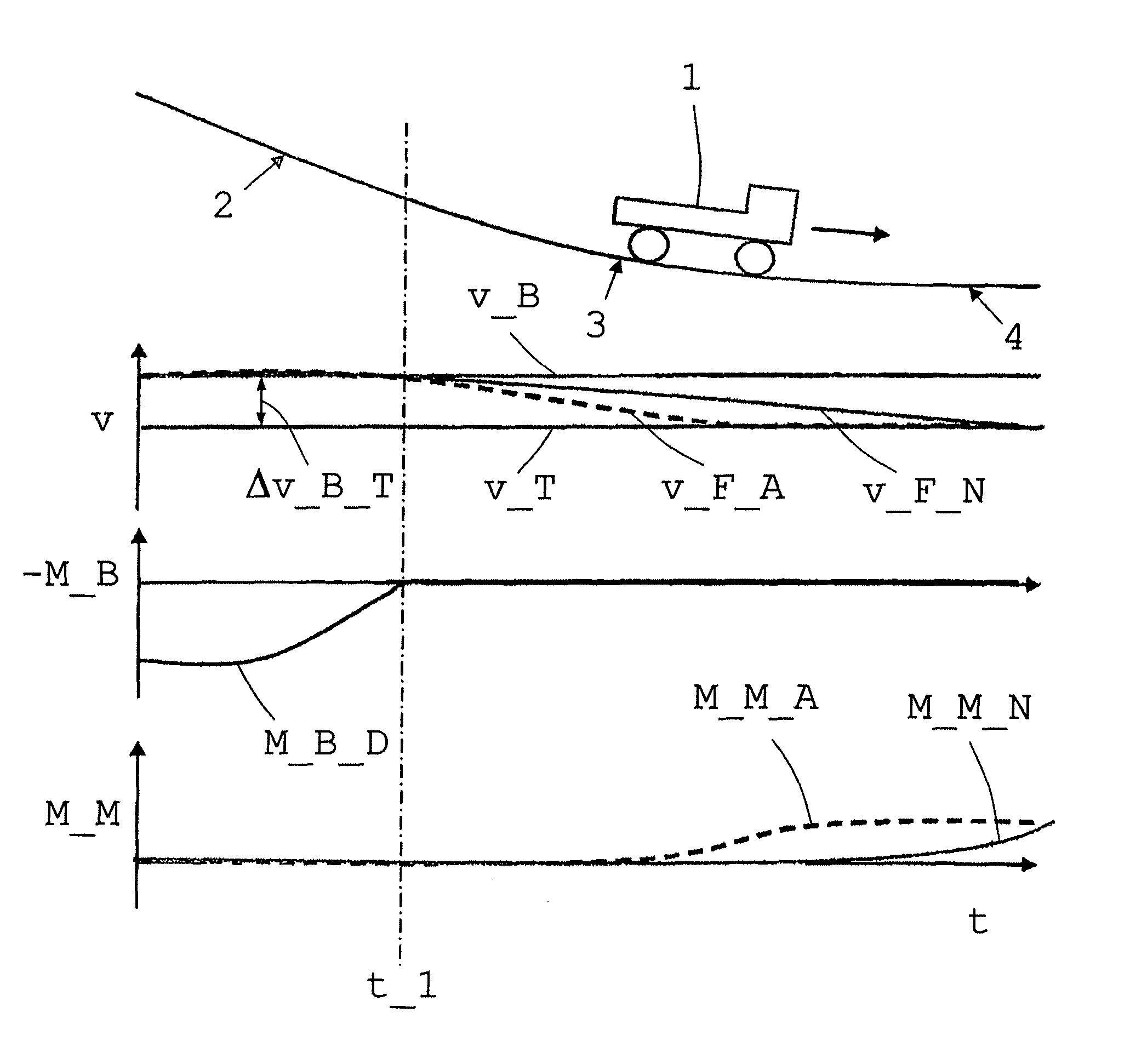
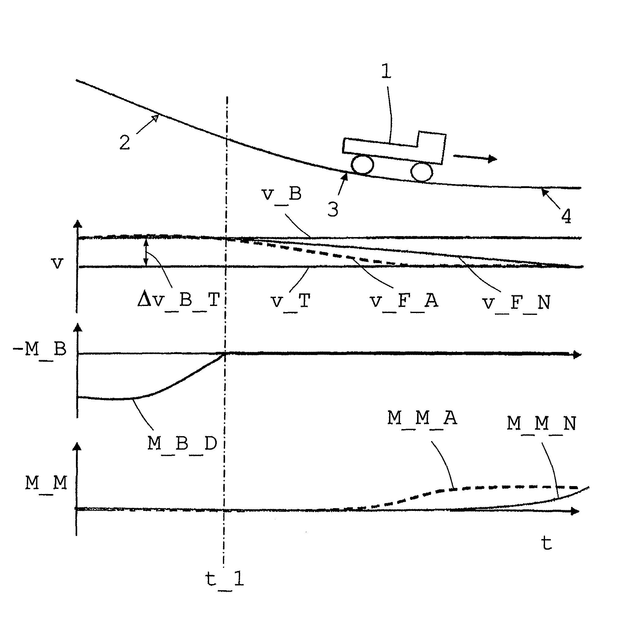
[0042]The commercial vehicle has an internal combustion engine and an automated single- or multi-group transmission with dog-shifted gears and transmission controls. Furthermore, the drive train has an auxiliary brake system designed e.g. as a hydrodynamic or electrodynamic retarder, and a Tempomat / Bremsomat system as a drive speed control device. Vehicles with such drive trains are known per se; consequently, the following description is restricted to a method according to the invention for controlling the rolling or coasting function of such a vehicle.

[0043]The method according to the invention basically involves interrupting the flow of power in the drive train in thrust mode instigated by transmission controls as soon as possible after a retarder shuts off and before entering a flat area at a different time from the Tempomat's request for engine torque when driving on a downhill gradient section while the rolling or coasting condition is satisfied, taking into account the functi...


PUM


Abstract

A method of controlling a rolling or coasting function of a vehicle with a drive train having a drive motor, an automatic or automated transmission, a controllable shifting means, a brake device and a drive speed control device. The vehicle speed is regulated by the drive speed control device and the braking device is activated, as needed, when driving on a downhill gradient section. To effectively and reliably use the rolling or coasting function in suitable driving situations, taking into account the influence of the driving speed control device, a rolling or a coasting condition for a downhill gradient taper is checked, when driving on the downhill gradient section, and, when the rolling or coasting condition is satisfied, the transmission controls interrupt the flow of power in the drive train before the vehicle entering a flat area, and / or before the driving speed control device generates an engine torque request.

Description

[0001]This application is a National Stage completion of PCT / EP2010 / 065297 filed Oct. 13, 2010, which claims priority from German patent application serial no. 10 2009 046 341.0 filed Nov. 3, 2009.FIELD OF THE INVENTION[0002]The invention relates to a method for controlling a rolling or coasting function of a vehicle.BACKGROUND OF THE INVENTION[0003]Saving energy and cost in the powertrain and reducing pollution from exhaust gas and noise emissions are current goals in vehicle development. In suitable driving situations, vehicles can be temporarily advanced without being driven in a rolling or coasting mode. When a motor vehicle is in rolling mode, the internal combustion engine can operate with minimized consumption and low emissions while idling as the vehicle rolls with a disengaged drive train. If the internal combustion engine is turned off in such a driving situation to further increase the savings effect, the vehicle moves in a so-called coasting mode. These functions are alr...

Claims


Application Information

Patent Timeline
Patent Type & Authority Patents(United States)
IPC IPC(8): B60W10/04B60W10/02B60W10/06B60W10/10B60W10/11B60W10/18B60W10/184B60W30/18F16H59/18F16H59/66
CPCB60W10/02B60W10/06B60W10/11B60W10/184B60W30/18072B60W2520/105B60W2550/142F16H59/66F16H2059/186B60W2552/15Y02T10/60
Inventor WURTHNER, MAIKSAUTER, INGOSTAUDINGER, JOACHIMKEMLER, JOHANNES
Owner ZF FRIEDRICHSHAFEN AG
Learn More