
Method and device for automatically managing the spacing of at least one following aircraft behind at least one target aircraft

Inactive Publication Date: 2015-01-13
AIRBUS OPERATIONS SAS
View PDF19 Cites 1 Cited by
  • Summary
  • Abstract
  • Description
  • Claims
  • Application Information

AI Technical Summary

Benefits of technology

The patent text describes a system for guiding an aircraft to a specific point. The system takes into account the current distance the aircraft is traveling, rather than a direct distance, to calculate speed control commands that will allow the aircraft to accurately reach the destination. This approach overcomes the problem of variation in acceleration and discomfort that can occur when using a direct distance. The system can also account for different flight paths and the effect of wind and temperature, resulting in better guidance and a more accurate indication of the aircraft's speed. The main advantage of this system is that it reduces the workload of the operator and ensures safe and accurate guidance even when the target aircraft does not follow its flight plan.

Problems solved by technology

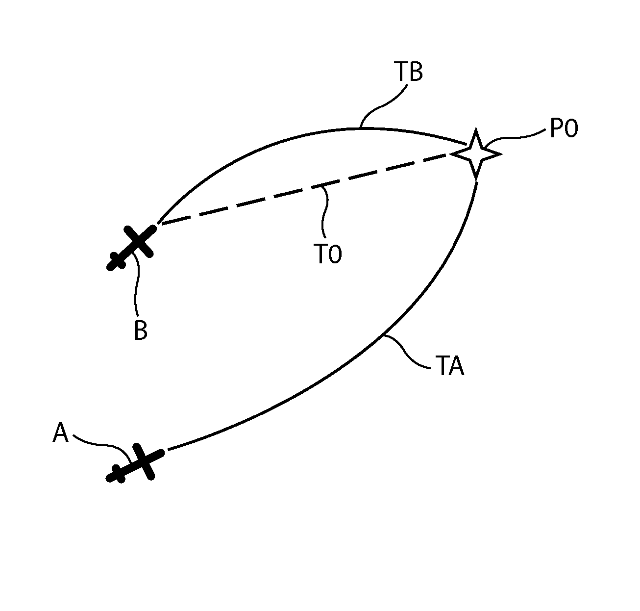
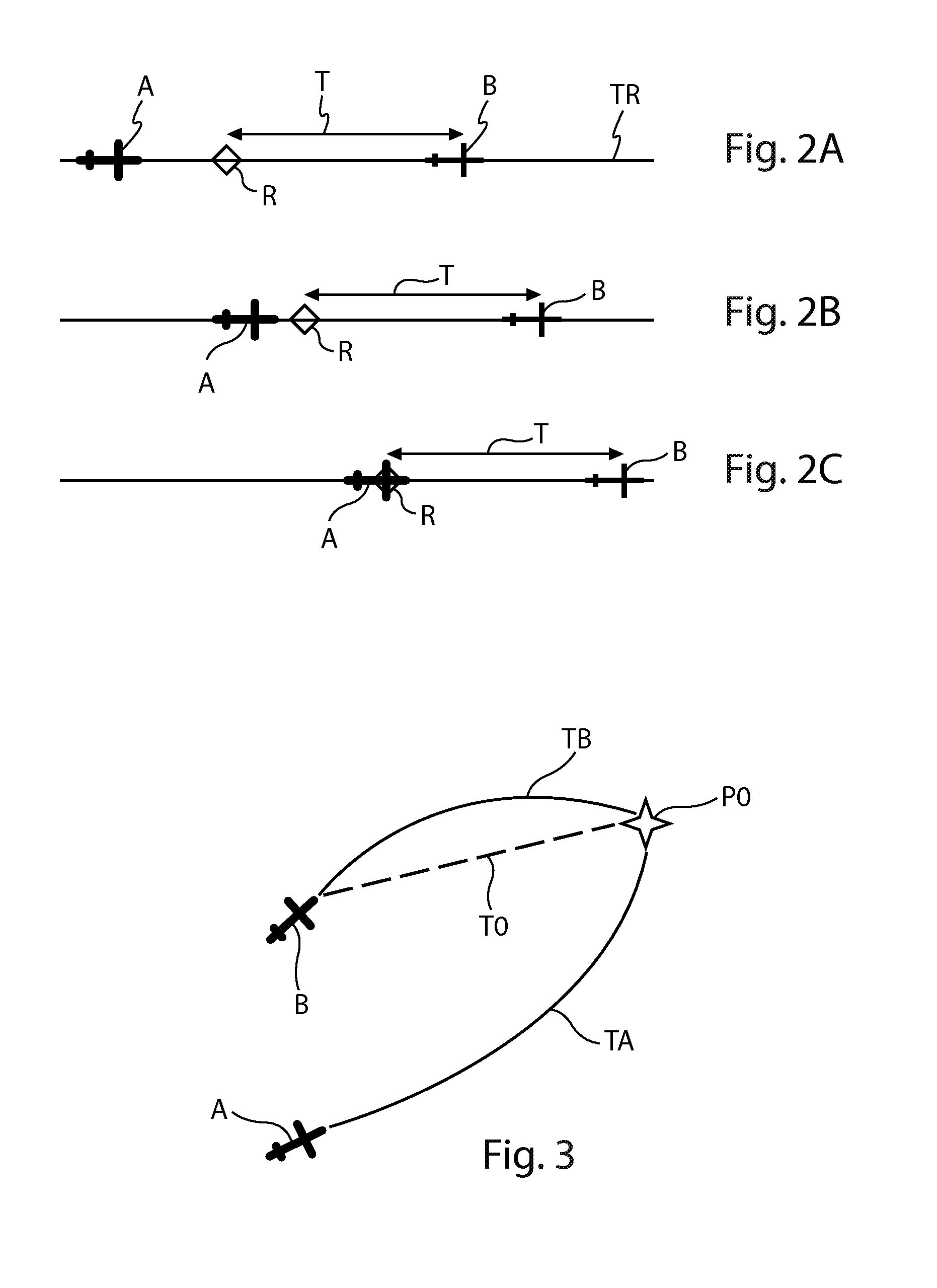
This assumption of direct flight (in other words following a rectilinear segment between the current position of the target aircraft and the position of the merge waypoint) does not however allow a correct and satisfactory acquisition of the spacing whenever the path of the target aircraft is significantly different from a direct path toward the merge waypoint.
Indeed, in such a situation, the target aircraft will take a significantly longer time to reach the merge waypoint than predicted.
Moreover, for flight paths having particularly complex geometries, the direct distance may even, over time, stop decreasing and locally re-increase.
The effect on the guidance of the following aircraft may consist of an unnecessary acceleration at the start of the acquisition, followed by an abrupt deceleration at the end of the acquisition, which can lead to a degradation in comfort and potentially an incapacity to perform a correct acquisition resulting in a cancellation of the maneuver.
As such a situation is not rare, it leads to a significant limitation of the possibility of using the usual acquisition function.

Method used


Image

  • Method and device for automatically managing the spacing of at least one following aircraft behind at least one target aircraft
  • Method and device for automatically managing the spacing of at least one following aircraft behind at least one target aircraft
  • Method and device for automatically managing the spacing of at least one following aircraft behind at least one target aircraft

Examples


first embodiment

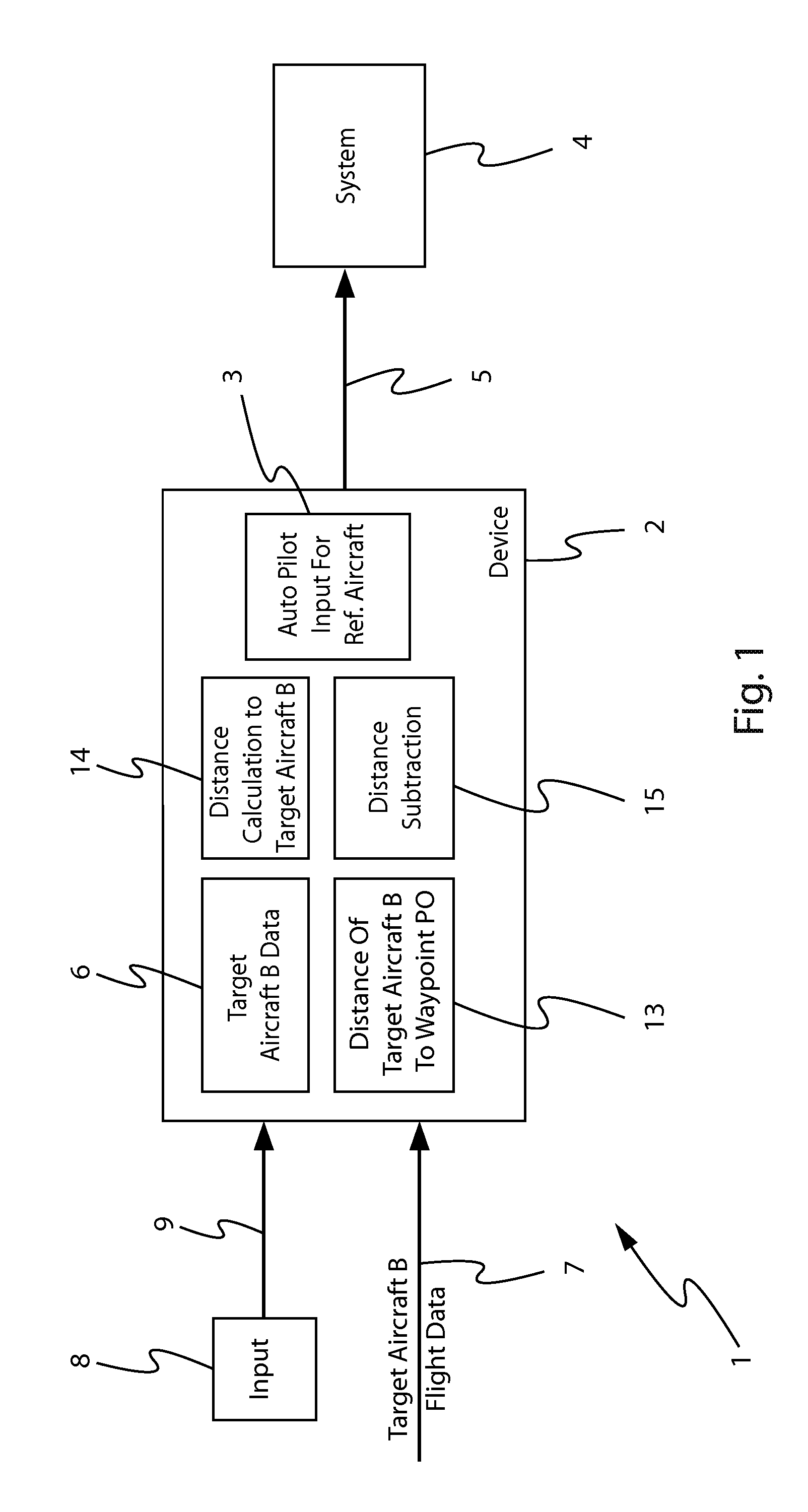
[0113]In a first embodiment, an operator inputs said value d0, which he has received from said air traffic controller, by means of usual input means (control ball, track ball, keyboard, etc.), forming for example a part of the means 8.

second embodiment

[0114]Furthermore, in a second embodiment, said value d0, which is received from said air traffic controller via a data transmission link, is input automatically into the device 2 (for example via the link 7) after validation by an operator, which notably allows the workload of the operator to be reduced.

[0115]In the framework of the present invention, the means 14 may implement various methods for calculating said second distance value d2.

[0116]In a first variant embodiment, said means 14 comprise integrated elements (not shown) for calculating said second distance value d2A(t) at the current time, by means of the following expression:

[0117]d⁢⁢2⁢A⁡(t)=∫t⁢⁢0t⁢v⁡(t)⁢ⅆt

in which:

[0118]t0 is said initial time;

[0119]t is the current time; and

[0120]v(t) is the speed of the target aircraft B, received via the link 7.

[0121]Furthermore, in a second variant embodiment, said means 14 comprise elements (integrated and not shown) for calculating said second distance value d2B(t) at the current t...


PUM


Abstract

The system (1) comprises means for determining the distance at the current time of the target aircraft (B) with respect to the merge waypoint (P0) along its path (TB), this distance being transmitted to calculation means in order to determine the speed control commands which are subsequently applied to the reference aircraft (A) in order for it to carry out the acquisition of the spacing at said merge waypoint (P0).

Description

[0001]This application and claims priority to FR 12 58501 filed 11 Sep. 2012, the entire contents of which is hereby incorporated by reference.BACKGROUND OF THE INVENTION[0002]1. Field of the Invention[0003]The present invention relates to a method and a system for automatic management of the spacing of at least one aircraft, referred to as reference aircraft, behind at least one other aircraft, referred to as target aircraft, preceding it.[0004]2. Discussion of Prior Art[0005]It is desirable, in order to maintain a spacing, to apply speed control commands to the reference aircraft (or following aircraft) such that they allow said reference aircraft to adopt the same position, the same speed, and the same acceleration as the target aircraft (or aircraft being followed) N seconds before the current time (or present time), N seconds corresponding to a predetermined period of time.[0006]The present invention may be applied to a cruising phase, in particular to make a fleet of aircraft,...

Claims


Application Information

Patent Timeline
IPC IPC(8): G05D1/10G05D1/12G08G5/00G08G9/02
CPCG05D1/12G05D1/104G08G5/00G08G5/0008G08G5/0021G08G5/0052G08G5/0078G08G9/02
Inventor RAYNAUD, SYLVAINGUILLERMIN, JEAN-CHRISTOPHE
Owner AIRBUS OPERATIONS SAS
Learn More