Converter system

a converter and system technology, applied in the field of new energy technology, can solve the problems of increasing system loss, difficult to transmit a large amount of power energy to the electric grid through only a single converter, and serious problems such as circular current caused

Active Publication Date: 2014-12-23
DELTA ELECTRONICS INC
View PDF48 Cites 2 Cited by
  • Summary
  • Abstract
  • Description
  • Claims
  • Application Information

AI Technical Summary

Benefits of technology

[0032]In order to solve the circular current problem, the converter system suppresses the circular current through the synchronous operation of rectifiers 102 and 302. For example, the converter system eliminates the circulation channel therein through a rectifier synchronous signal that is inputted to the side of the rectifier module 10 and the side of the rectifier module 30, as shown in FIG. 1.

Problems solved by technology

While the capacity of power generation systems is becoming larger and larger, faced with capacity bottlenecks of modern electronic components, it is not easy to transmit a large amount of power energy to an electric grid through only a single converter.
Nevertheless, in multiple converter systems which are connected in parallel, once there is a circulation channel, a serious problem of circular current is caused.
The circular current only flowing among parallel connected converters not only increases system loss, but also reduces system efficiency, so that a large amount of heat is generated in the switch and even more seriously the switch is burned.
Furthermore, the circular current also causes unbalancing current, so that the current stress applied on the power switch is not balanced, which reduces the usage life of the power switch and limits the increased capacity of the total system.
Moreover, the circular current also results in distortion of the three-phase current and increases the total harmonic distortion (THD), so that the grid connection of the system is not easily realized.
However, in the above mentioned solutions the isolation transformer has a large volume, which not only increases the cost of the system, but also greatly reduces the power density of the system.
However, such solution can not be used in different situations.

Method used


Image

  • Converter system
  • Converter system
  • Converter system

Examples


Embodiment Construction

[0027]In order to make the description of the present disclosure more detailed and more comprehensive, various embodiments are described below with reference to the accompanying drawings. The same reference numbers are used in the drawings to refer to the same or like elements. However, those skilled in the art should understand that the embodiments described below are not used for limiting the scope of the present disclosure. Moreover, the accompanying drawings are only illustrative and are not made according to actual size.

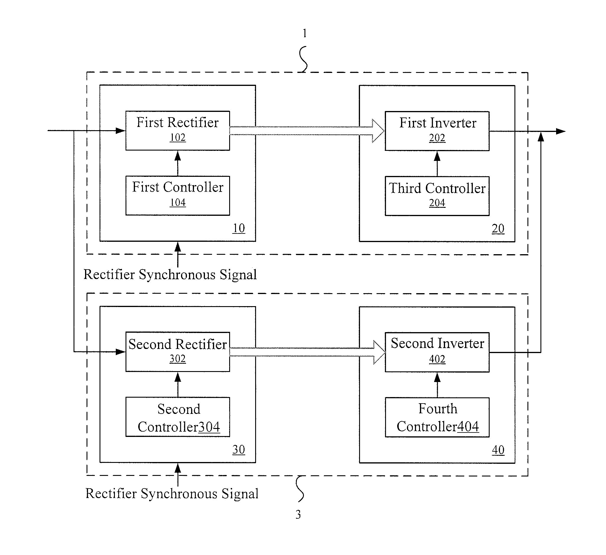
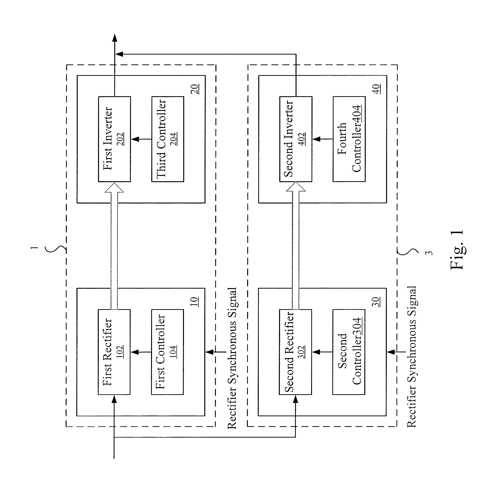
[0028]As previously mentioned, the conventional parallel inverter technology, which can significantly increase the total current without increasing the current stress of a single power switch, is gradually becoming an active area of research and development. For example, under a given input power, through parallel technology a power switch having a low power grade is used so as to reduce the manufacturing cost of the product. However, when converters are connect...


PUM


Abstract

The present disclosure discloses a converter system, which at least includes the first and second back-to-back converters. The first back-to-back converter includes a first rectifier module and a first inverter module. The first rectifier module is used to convert a first AC voltage to a first DC voltage. The first inverter module is used to convert the first DC voltage to a second AC voltage. The second back-to-back converter includes a second rectifier module and a second inverter module. The second rectifier module is used to convert the first AC voltage to a second DC voltage. The second inverter module is used to convert the second DC voltage to the second AC voltage. The converter system can suppress the circular current through the synchronous operation of the first and second rectifiers or the synchronous operation of the first and second inverters.

Description

RELATED APPLICATIONS[0001]This application claims priority to China Application Serial Number 201210066923.8, filed Mar. 9, 2012, which is herein incorporated by reference.BACKGROUND[0002]1. Field of Invention[0003]The present disclosure relates to the field of new energy technology and the field of power electronic technology. More particularly, the present disclosure relates to a converter system applied in the area of new energy technology.[0004]2. Description of Related Art[0005]With the ever-increasing seriousness of energy-related issues in recent times, the development of new energy technology is gradually gaining the attention of those involved in research and development in various fields. While the capacity of power generation systems is becoming larger and larger, faced with capacity bottlenecks of modern electronic components, it is not easy to transmit a large amount of power energy to an electric grid through only a single converter.[0006]In order to solve the problems...

Claims


Application Information

Patent Timeline
Patent Type & Authority Patents(United States)
IPC IPC(8): H02P1/30H02P3/00
CPCH02M5/458H02P27/08H02M7/493
Inventor LI, LINTAN, JING-TAOWU, HONG-YANG
Owner DELTA ELECTRONICS INC
Why Eureka
Try Eureka