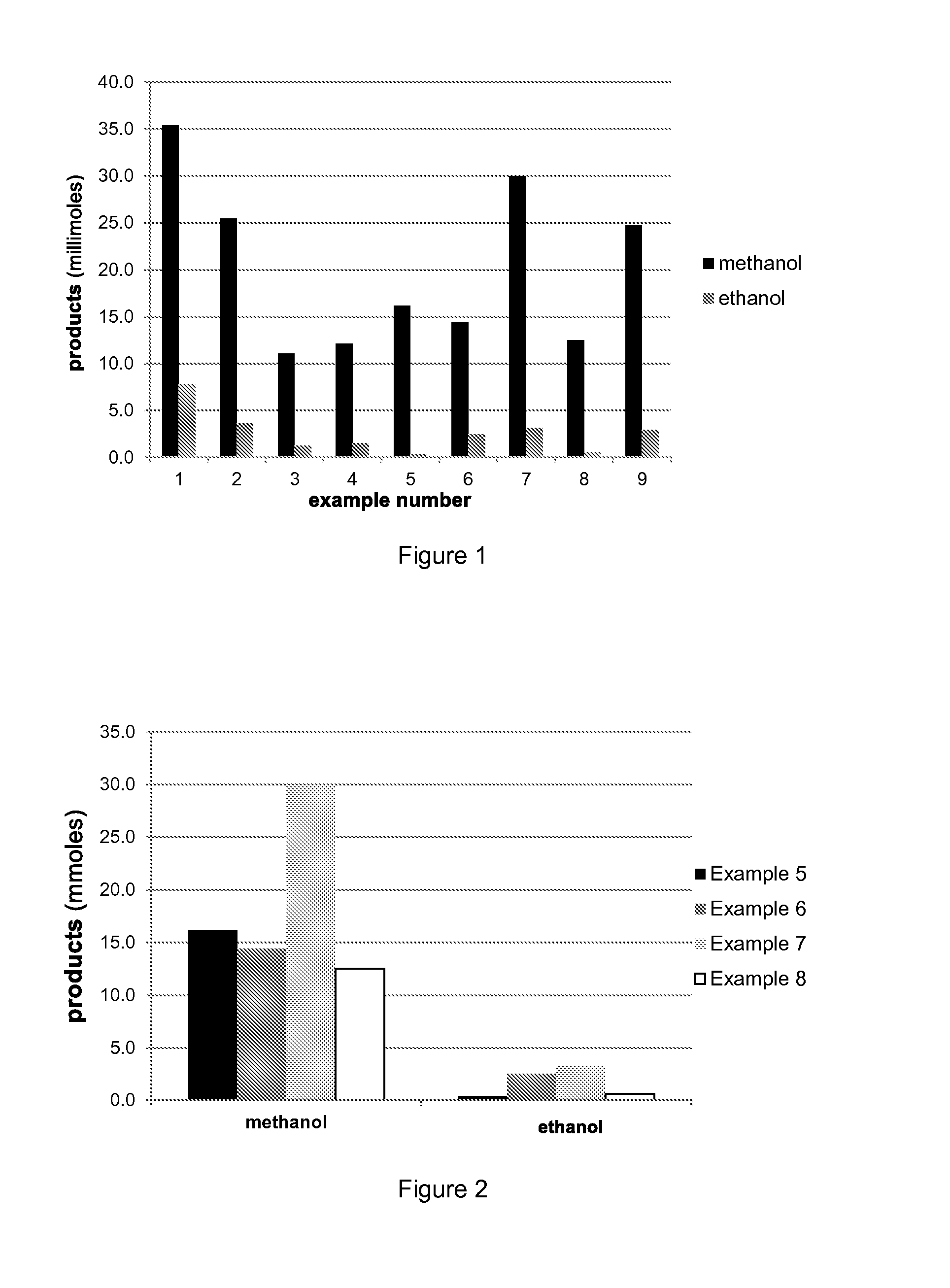
Production of methanol and ethanol from CO or CO2
a technology of methanol and ethanol, which is applied in the direction of physical/chemical process catalysts, bulk chemical production, organic compound/hydride/coordination complex catalysts, etc., and can solve the problem that jp '449 also does not disclose the use of molten salt as the reaction solven
- Summary
- Abstract
- Description
- Claims
- Application Information
AI Technical Summary
Problems solved by technology
Method used
Image
Examples
example 2
Standard with 1:1 CO / H2 but Substitute 10 MPa CO2, Total Pressure same at 25 MPa
[0073]The clean and dry autoclave was assembled, and 14.503 g of [PBu4]Br (42.74 mmol), 0.500 g of Ru3(CO)12 (2.34 mmol Ru), and 0.415 g of [HPBu3]Br (1.47 mmol) were added to the autoclave. The autoclave was pressurized to 1 MPa with CO / H2 (1:1), and then the pressure was released to ambient pressure to purge the autoclave. This step was repeated five times. The autoclave was then charged with CO / H2 (1:1) to 9.3 MPa of pressure and left overnight.
[0074]The following morning, the system was checked for leaks, and the heater and stirrer were switched on. When the temperature reached 200° C., the pressure inside the autoclave was reduced to 14.0 MPa, and CO2 was added until the pressure was 24.0 MPa. Next, CO / H2 (1:1) was added again until the pressure was 25.0 MPa. The Picolog datapoint was noted, and the mass flow controller datalogging was switched on. The stirring speed was increased to a setting of 9,...
example 5
Reaction of CO2 and H2
[0081]The clean and dry autoclave was assembled, and 14.502 g of [PBu4]Br (42.734 mmol), 0.500 g of Ru3(CO)12 (2.34 mmol Ru), and 0.415 g of [HPBu3]Br (1.47 mmol) were added to the autoclave. The autoclave was pressurized to 1 MPa with gas, and then the pressure was released to ambient pressure to purge the autoclave. Synthesis gas, CO / H2 (1:2), was used three times, and then H2 was used four times to ensure complete removal of air.
[0082]The system was initially pressurized to 12 MPa with H2, then heated to 50° C. The pressure was then adjusted to 12.6 MPa with H2. Next, 6.0 MPa of CO2 were added to produce a total pressure was 19.0. The system was tested for leaks, the heater was switched off, and the system was left under pressure overnight.
[0083]The following morning, the system was tested for leaks again. Then, the heater and stirrer were switched on. When the temperature reached 200° C., the time was noted, and the reaction was allowed to proceed for 4 ho...
example 7
Reaction of CO and H2O
[0092]The clean and dry autoclave was assembled, and 14.502 g of [PBu4]Br (42.73 mmol), 0.500 g of Ru3(CO)12 (2.34 mmol Ru), and 0.415 g of [HPBu3]Br (1.47 mmol) were added to the autoclave. The autoclave was pressurized to 1 MPa with gas, and then the pressure was released to ambient pressure to purge the autoclave. Synthesis gas, CO / H2 (1:2), was used three times, and then 4.3 mL of water was added by syringe under a positive flow of CO / H2.
[0093]Next, the autoclave was pressurized to 3.3 MPa with CO, then heated to 50° C. The pressure was then adjusted to 3.2 MPa. After that, 9.4 MPa of CO were added to produce a total pressure of 12.6 MPa. The system was tested for leaks, the heater was switched off, and the system was left under pressure overnight.
[0094]The following morning, the system was tested for leaks again. Then, as in Example 5, the heater and stirrer were switched on. When the temperature reached 200° C., the time was noted, and the reaction was al...
PUM
| Property | Measurement | Unit |
|---|---|---|
| temperature | aaaaa | aaaaa |
| pressure | aaaaa | aaaaa |
| temperatures | aaaaa | aaaaa |
Abstract
Description
Claims
Application Information
 - R&D
- Intellectual Property
- Life Sciences
- Materials
- Tech Scout
- Unparalleled Data Quality
- Higher Quality Content
- 60% Fewer Hallucinations
Browse by: Latest US Patents, China's latest patents, Technical Efficacy Thesaurus, Application Domain, Technology Topic, Popular Technical Reports.
© 2025 PatSnap. All rights reserved.Legal|Privacy policy|Modern Slavery Act Transparency Statement|Sitemap|About US| Contact US: help@patsnap.com


