Adjustable buckle and collar
a clip buckle and adjustable technology, applied in the field of adjustable clip buckles, can solve the problems of easy overtightening of the strap, difficulty in releasing, and inability to adjust the spacing between the strap ends when fastened, and achieve the effect of easy and rapid attachment of the leash to the collar, easy and rapid detachment, and rapid control
- Summary
- Abstract
- Description
- Claims
- Application Information
AI Technical Summary
Benefits of technology
Problems solved by technology
Method used
Image
Examples
first embodiment
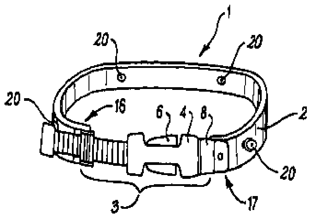
[0074]FIG. 1 shows a schematic perspective view of an animal collar according to the second aspect of the invention with a clip buckle assembly according to the first aspect of the invention.
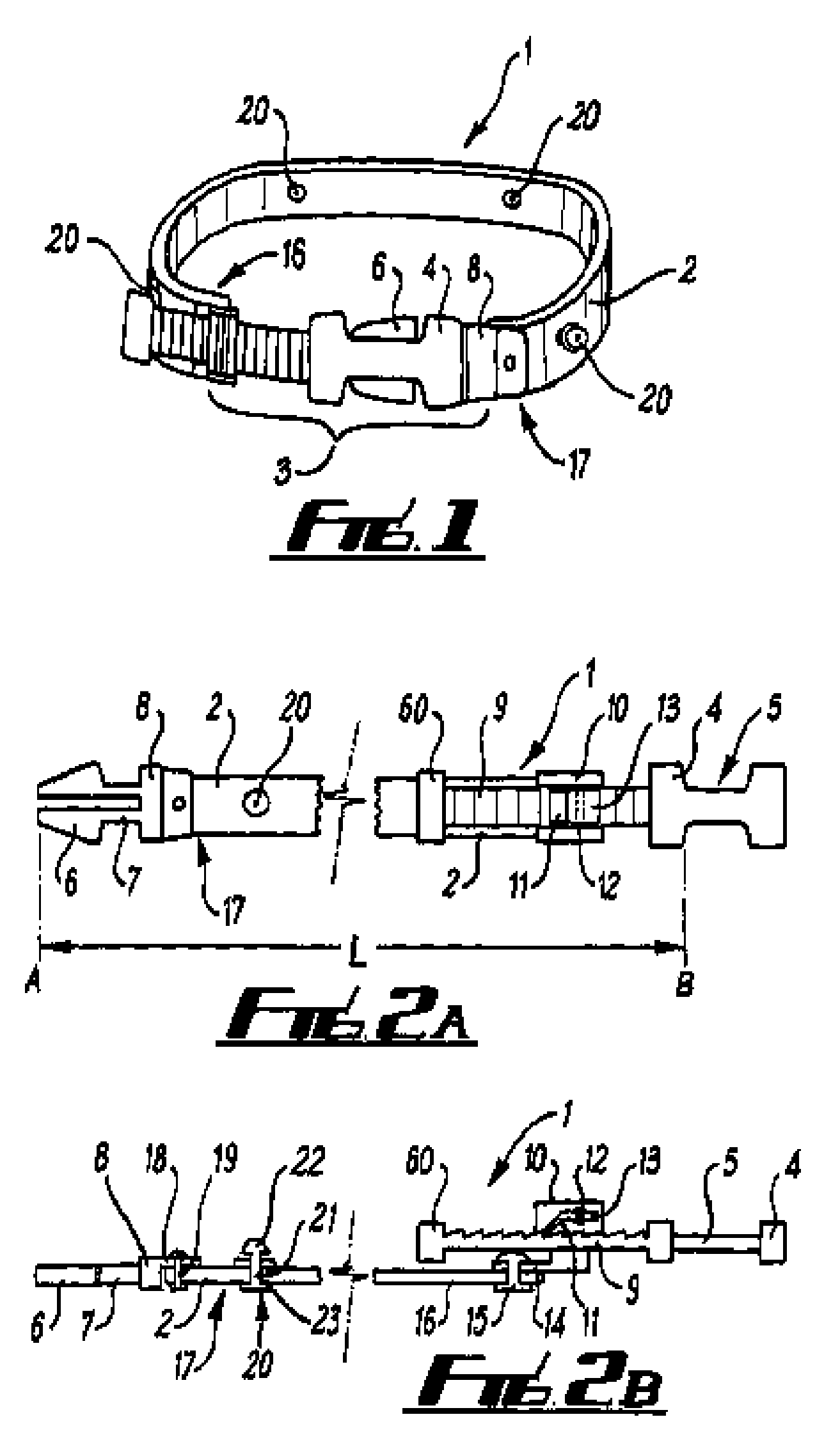
[0075]FIGS. 2A and 2B show plan and cross-sectional side views of the collar of the first embodiment with the clip buckle assembly in a disengaged state and with the strap extended to open out the collar.
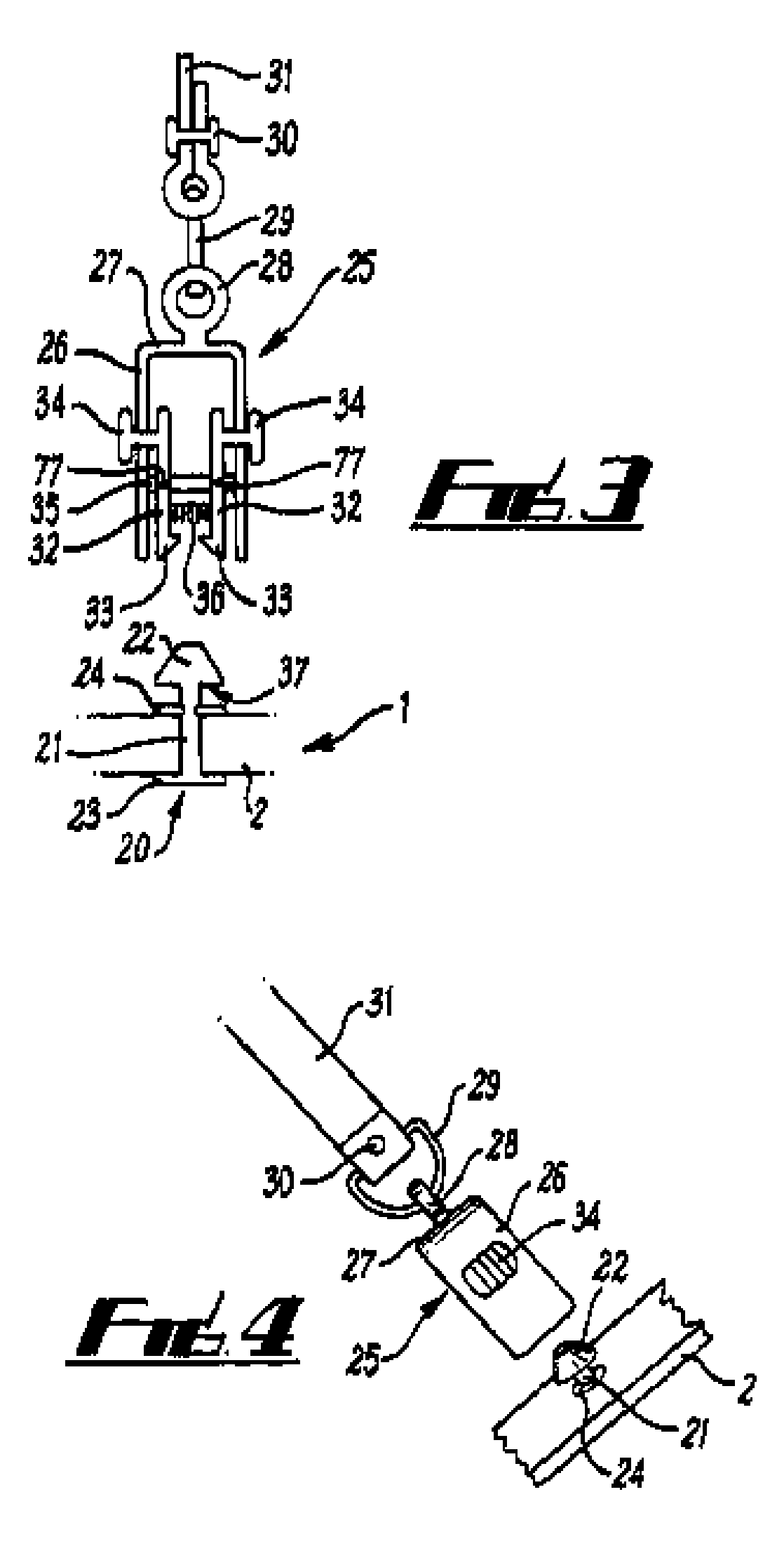
[0076]FIG. 3 shows a cross sectional schematic side view of a quick-couple, quick-release male-female coupling arrangement used for attaching a leash to the collar of the first embodiment.
[0077]FIG. 4 shows a schematic perspective view of the coupling arrangement as shown in FIG. 3.
second embodiment
[0078]FIGS. 5A to 5B show plan, side and bottom plan views of an animal collar according to the second aspect of the invention, having a clip buckle assembly according to the first aspect of the invention.
[0079]FIGS. 6A to 6C show further details of the clip buckle assembly of the second embodiment shown in FIGS. 5A to 5C. FIG. 6A shows a side cross-sectional through the clip buckle assembly a long axis X-X, as shown in FIG. 6B. FIG. 6B shows a plan view and FIG. 6C shows a conventional side view.
[0080]FIGS. 7A to 7E show details of the interlockable connection joints used in the second embodiment of the animal collar, as shown in FIGS. 5 and 6. For these interlockable connection joints, a D-ring is used as a connection key. FIG. 7A shows a side view of the interlocked connection joint with FIG. 7B showing a plan view. FIG. 7C shows a perspective view with FIGS. 7D and 7E showing perspective views of the individual, first and second interlocking members of the interlocking connectio...
PUM
 Abstract
Description
Claims
Application Information
 - R&D
- Intellectual Property
- Life Sciences
- Materials
- Tech Scout
- Unparalleled Data Quality
- Higher Quality Content
- 60% Fewer Hallucinations
Browse by: Latest US Patents, China's latest patents, Technical Efficacy Thesaurus, Application Domain, Technology Topic, Popular Technical Reports.
© 2025 PatSnap. All rights reserved.Legal|Privacy policy|Modern Slavery Act Transparency Statement|Sitemap|About US| Contact US: help@patsnap.com


