
Side dressing fertilizer coulter

a fertilizer coulter and side dressing technology, applied in the field of side dressing fertilizer coulter, can solve the problems of difficult to maintain a constant depth of fertilizer and/or seed, and the need for row clearing devices with higher residue levels,

Active Publication Date: 2014-12-16
DAWN EQUIPMENT COMPANY
View PDF344 Cites 68 Cited by
  • Summary
  • Abstract
  • Description
  • Claims
  • Application Information

AI Technical Summary

Benefits of technology

The patent text describes an agricultural side dressing fertilizer coulter row unit that can be attached to a tractor and used to apply fertilizer to soil. The unit includes a coulter wheel for making a slit in the soil, a liquid fertilizer dispenser for dispensing fertilizer into the slit, and a closing wheel for closing the slit after fertilizer has been dispensed. A biasing element, such as an air spring, is attached to the unit to control the downward force applied by the coulter wheel and the closing wheel against the soil. The position of the fertilizer dispenser and closing wheel can be adjusted to control the amount of fertilizer dispensed and the degree of soil closure. The technical effects of this invention are improved efficiency and accuracy in soil application of fertilizer and reduced soil compaction caused by excessive force applied by the coulter wheel and closing wheel against the soil.

Problems solved by technology

As an agricultural planter row unit travels across fields with variable soil types, soil moisture, residue levels and topography, it is difficult to maintain a constant depth of fertilizer and / or seed due to the changing conditions.
This problem is complicated by the fact that the optimum pressure for any given soil condition can be different for different implements carried by the same row unit.
On the other hand, farming with higher residue levels may require greater increases in the down pressures for the row-clearing devices than for the opening and closing implements.

Method used


Image

  • Side dressing fertilizer coulter
  • Side dressing fertilizer coulter
  • Side dressing fertilizer coulter

Examples


Embodiment Construction

[0022]Although the invention will be described in connection with certain preferred embodiments, it will be understood that the invention is not limited to those particular embodiments. On the contrary, the invention is intended to cover all alternatives, modifications, and equivalent arrangements as may be included within the spirit and scope of the invention as defined by the appended claims.

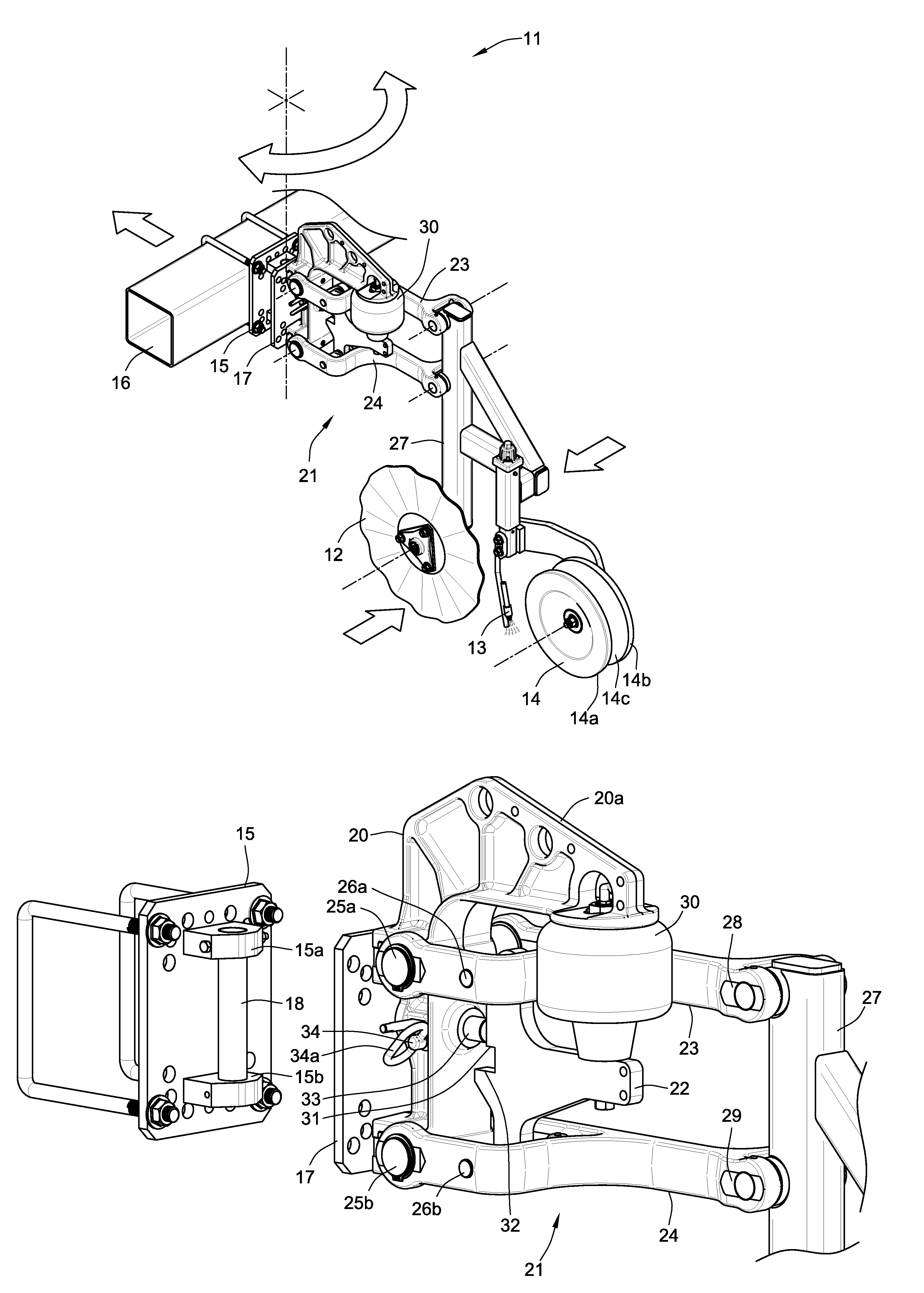
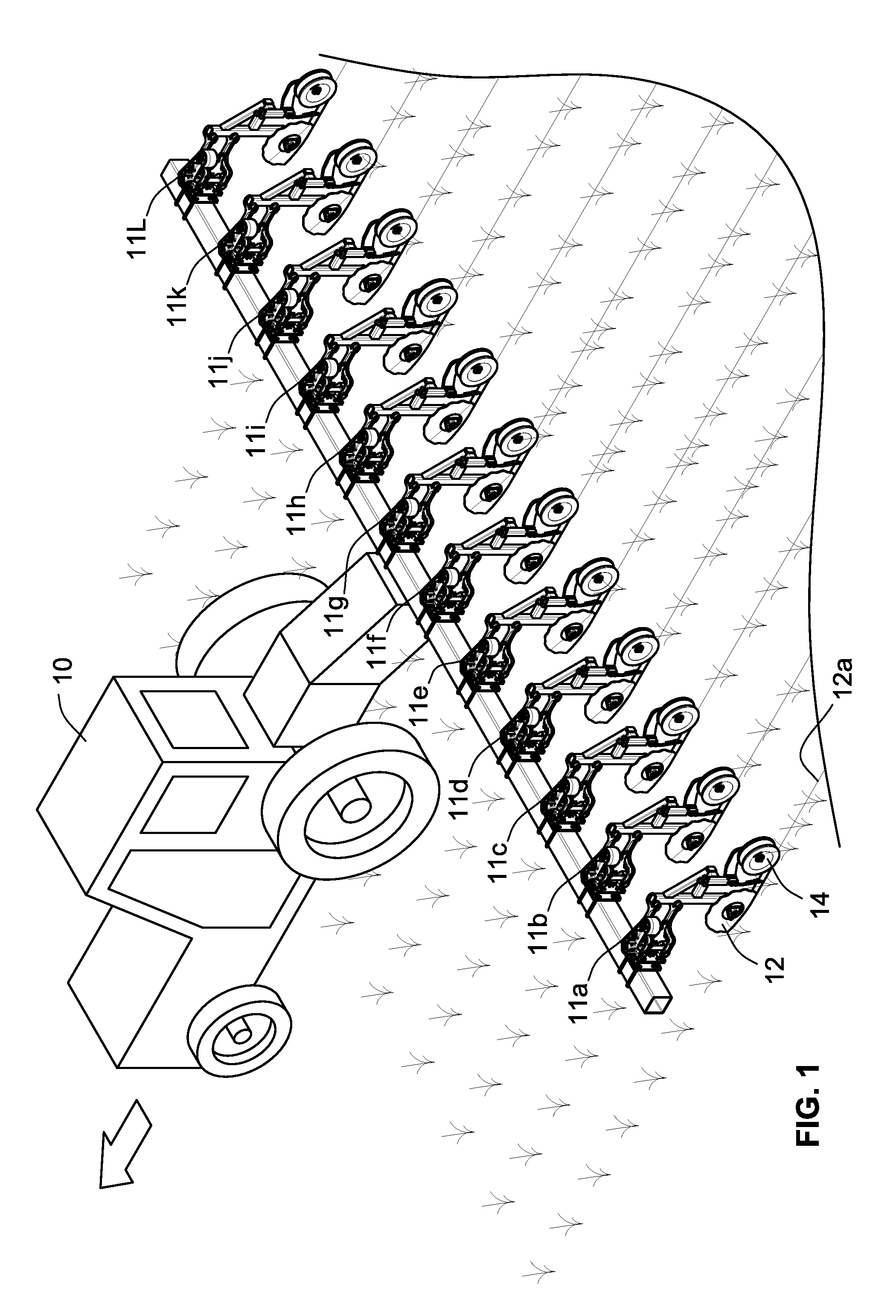
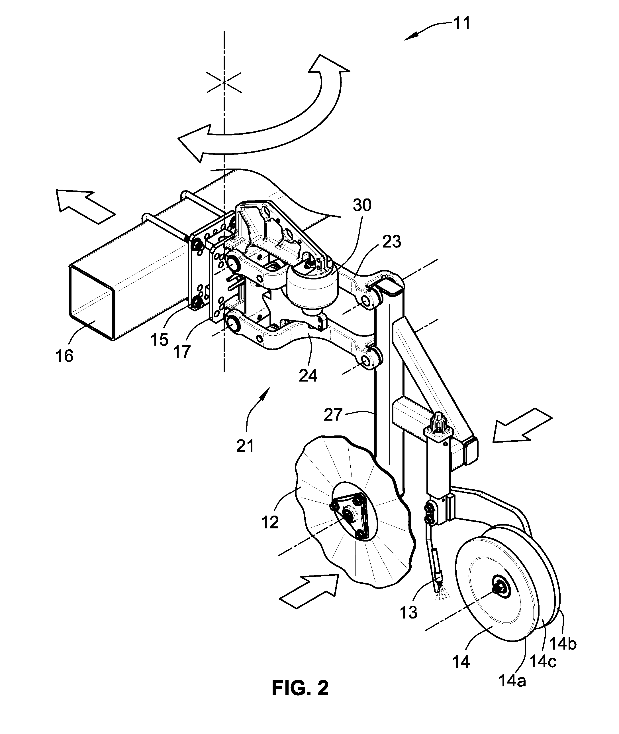
[0023]Turning now to the drawings and referring first to FIG. 1, a tractor 10 is shown pulling multiple side dressing fertilizer coulter row units 11a-111 through a field that has been planted. The crop is at a seedling stage, when fertilizer is typically applied as a “side dressing,” i.e., slightly offset laterally from each row of seedlings. As can be seen more clearly in FIG. 2, each of the fertilizer coulter row units 11a-111 includes a coulter wheel 12 for forming a slit in the soil, and at least one dispensing device 13 for depositing liquid fertilizer into the slit, and a closing wheel ...


PUM


Abstract

An agricultural side dressing fertilizer coulter row unit includes a first attachment member adapted to be rigidly connected to a towing frame, and a second attachment member pivotably coupled to the first attachment member for pivoting movement about a substantially vertical axis. A linkage is pivotably coupled to the second attachment member for pivoting movement of the trailing end of the linkage relative to the second attachment member, and a tool-carrying stem pivotably coupled to the trailing end of the linkage carries a rotatably mounted coulter wheel for forming a slit in the soil, a liquid fertilizer dispenser for dispensing fertilizer, and a rotatably mounted closing wheel for closing the slit. A biasing element is pivotably attached to the linkage and coupled to the second attachment member for urging the stem downwardly with a controllable force.

Description

FIELD OF THE INVENTION[0001]The present invention relates generally to agricultural implements and, more particularly, to a side dressing fertilizer coulter.BACKGROUND OF THE INVENTION[0002]As an agricultural planter row unit travels across fields with variable soil types, soil moisture, residue levels and topography, it is difficult to maintain a constant depth of fertilizer and / or seed due to the changing conditions. This problem is complicated by the fact that the optimum pressure for any given soil condition can be different for different implements carried by the same row unit. For example, hard soil might require increasing the down pressure of the soil-opening implement more than the down pressure of residue-clearing devices and closing implements carried on the same row unit. On the other hand, farming with higher residue levels may require greater increases in the down pressures for the row-clearing devices than for the opening and closing implements.[0003]As computers and ...

Claims


Application Information

Patent Timeline
Patent Type & Authority Patents(United States)
IPC IPC(8): A01C23/02
CPCA01C23/022A01C7/208
Inventor BASSETT, JOSEPH, D.
Owner DAWN EQUIPMENT COMPANY
Learn More