
Clot retrieval system

a retrieval system and clot technology, applied in the field of deployable systems, can solve the problems of risk of further ischemia, limited removal of intracranial obstructions, and critical time in removing clots, and achieve the effects of reducing the risk of vessel injury, and reducing the risk of ischemia

Active Publication Date: 2014-12-02
LEGACY VENTURES
View PDF25 Cites 67 Cited by
  • Summary
  • Abstract
  • Description
  • Claims
  • Application Information

AI Technical Summary

Benefits of technology

The patent text describes a device that can adjust the height and width of its distal body and the middle portion can expand relative to the distal and proximal tubes. The technical effect of this invention is that it provides a more flexible and adjustable device for performing medical procedures.

Problems solved by technology

Needless to say, when a blood clot creates such a blockage, time in removing the clot is critical.
The removal of intracranial obstructions is limited by several factors, such as the distance of the intracranial obstruction from the femoral access site, the tortuosity (twists and turns in the artery as it enters the base of the skull) of the cervical and proximal intracranial vasculature, the small size of the vessels and the extremely thin walls of intracranial vessels, which lack a significant muscular layer.
The device should be retrievable without the need for proximal occlusion of the vessel, which carries risk of further ischemia and risk of vessel injury.
Currently available intravascular thrombus and foreign body removal devices lack several of these features.
All the devices are ineffectual at removing organized hard thrombus that embolize to the brain from the heart and from atherosclerotic proximal vessels.
Most of the time, the device fails to dislodge the thrombus from the wall of the vessel and often, even when successfully dislodging the thrombus, the thrombus embolizes into another or the same vessel due to the open ended nature of the device.
The device is ineffective at removing hard, organized thrombus which has embolized from the heart, cholesterol plaque from proximal feeding arteries and other foreign bodies.
Again, these devices are ineffectual at treating hard thrombus.
Upon retrieval of the devices, the clot remains or is broken up into several pieces which embolize to vessels further along the vessel.

Method used


Image

  • Clot retrieval system
  • Clot retrieval system
  • Clot retrieval system

Examples


Embodiment Construction

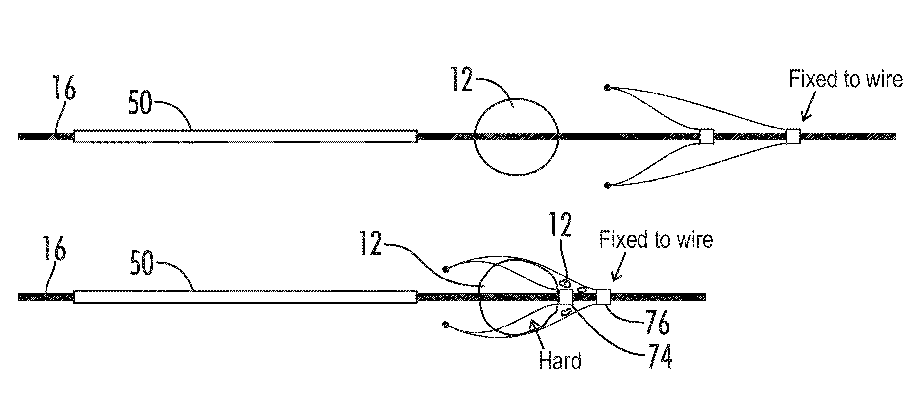
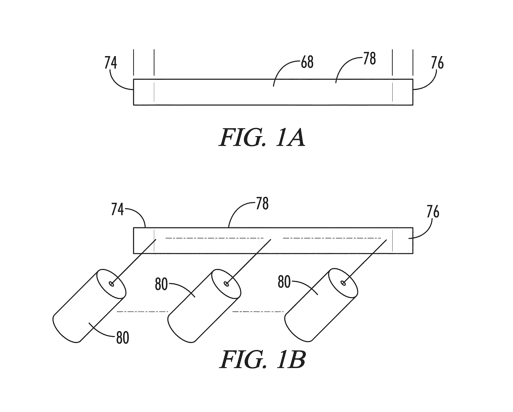
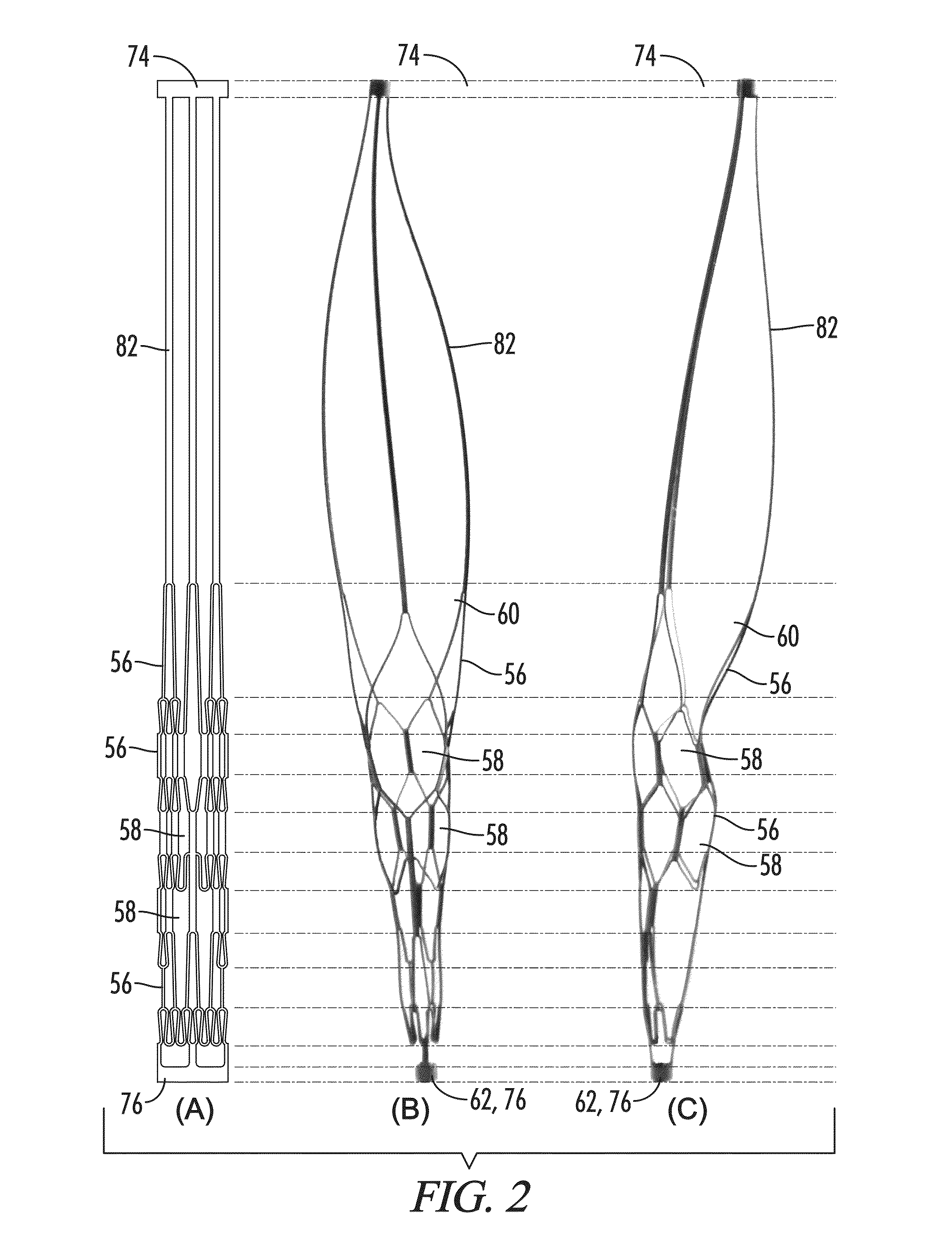
[0039]With reference to FIGS. 1-10, the present disclosure provides a deployable system, generally designated by the numeral 10, for removing an obstruction such as a blood clot 12 or other object from a blood vessel 14 or other interior lumen of an animal. In addition to a blood clot 12, the obstruction may be, for example, extruded coils during aneurysm treatment, intravascular embolic material such as onyx or other obstructions requiring mechanical intravascular removal from small distal vessels. In the drawings, not all reference numbers are included in each drawing for the sake of clarity.

[0040]Referring further to FIGS. 1-10, the deployable system 10 includes a pull wire 16 that has a proximal end (not shown) and a distal end 20. Optionally, the diameter of the pull wire is between about 0.008 inches and about 0.051 inches.

[0041]The system 10 further includes a distal body 22, which is attached to the pull wire 16. The distal body 22 has a proximal end 24, a distal end 26, an ...


PUM


Abstract

The present invention relates to a system for removing obstructions and other objects within a blood vessel or other interior lumen of an animal. The system may be deployed in the lumen from a catheter and includes a pull wire having a proximal end and a distal end, and a distal body. Optionally, the distal body includes a plurality of memory metal strips that form a closeable claw that is used to capture the obstruction. Optionally, the memory metal strips are connected to a proximal hub that is slideable along at least a segment of the pull wire and the memory metal strips are moved towards each other and towards the pull wire by moving the proximal hub distally towards a stationary distal hub, which in turn, causes the claw to close and capture the obstruction. The present invention also relates to methods of making and using such systems.

Description

BACKGROUND[0001]1. Technical Field[0002]The present invention relates to a deployable system for removing a blood clot or other object from a lumen of an animal.[0003]2. Background of the Invention[0004]Acute ischemic strokes develop when a blood clot (thrombus) blocks an artery supplying blood to the brain. Needless to say, when a blood clot creates such a blockage, time in removing the clot is critical.[0005]The removal of intracranial obstructions is limited by several factors, such as the distance of the intracranial obstruction from the femoral access site, the tortuosity (twists and turns in the artery as it enters the base of the skull) of the cervical and proximal intracranial vasculature, the small size of the vessels and the extremely thin walls of intracranial vessels, which lack a significant muscular layer. These limitations require a device to be small and flexible enough to navigate through tortuous vessels within a guide catheter and microcatheter, expand after deliv...

Claims


Application Information

Patent Timeline
Patent Type & Authority Patents(United States)
IPC IPC(8): A61M29/00A61B17/221
CPCA61B17/221A61B2017/2212A61B2017/00867
Inventor ULM, III, ARTHUR JOHN
Owner LEGACY VENTURES
Learn More