Electronic sphygmomanometer and blood pressure measurement control method
a technology of electronic sphygmomanometer and control method, which is applied in the field of electronic sphygmomanometer and blood pressure measurement control method, can solve the problem that the measurement method cannot be flexibly switched according to the person to be measured
- Summary
- Abstract
- Description
- Claims
- Application Information
AI Technical Summary
Benefits of technology
Problems solved by technology
Method used
Image
Examples
first embodiment
[First Embodiment]
[0044]The outer appearance and the configuration of an electronic sphygmomanometer (hereinafter abbreviated as “sphygmomanometer”) according to a first embodiment of the present invention will be described first.
(Regarding Outer Appearance)
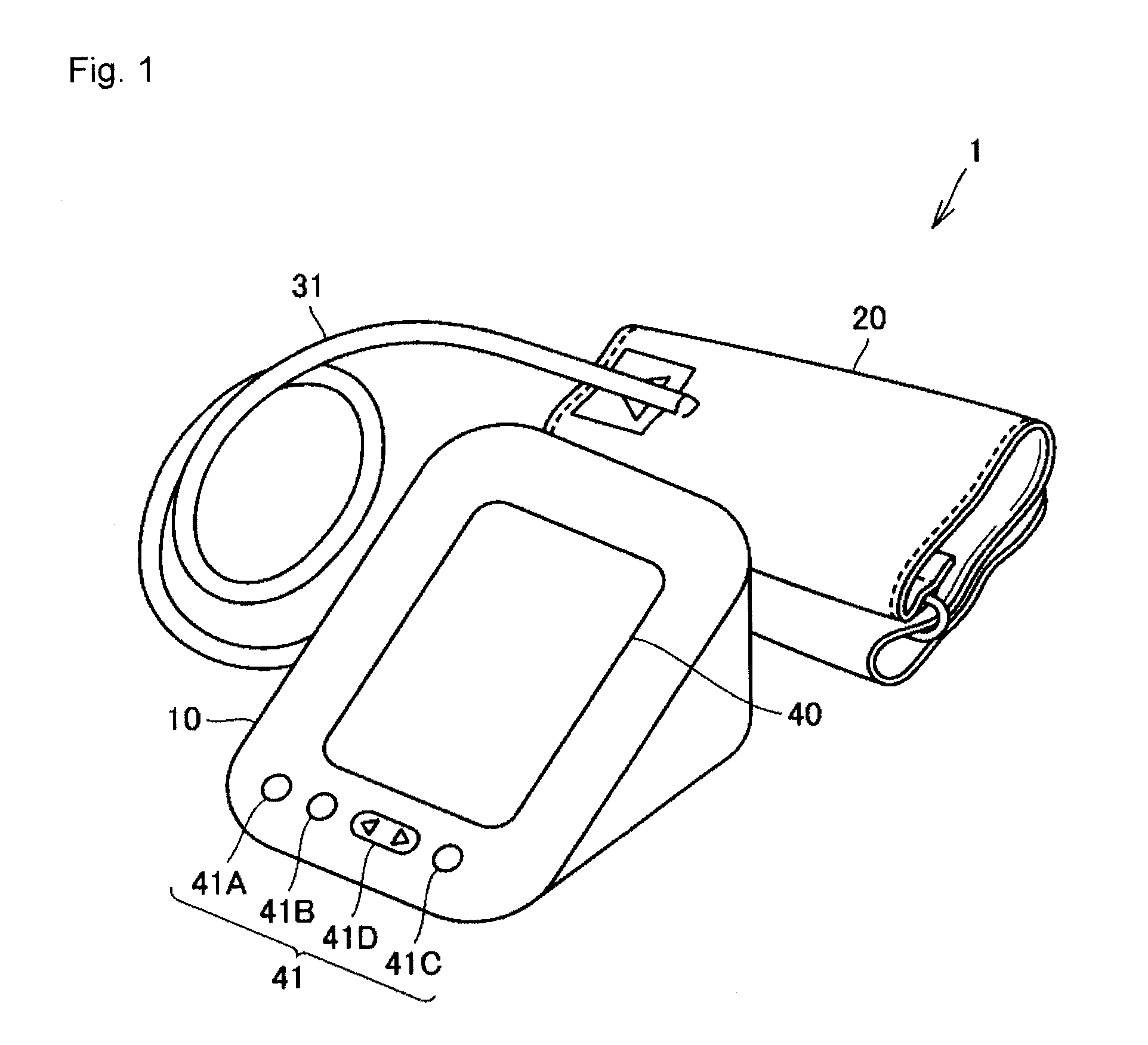
[0045]FIG. 1 is a perspective view of an outer appearance of a sphygmomanometer 1 according to a first embodiment of the present invention. The sphygmomanometer 1 measures the blood pressure according to the oscillometric method.
[0046]With reference to FIG. 1, the sphygmomanometer 1 includes a main body 10, a cuff 20 that can be wrapped around a predetermined measurement site (e.g., upper arm) of the person to be measured, and an air tube 31 for connecting the main body 10 and the cuff 20. A display unit 40 configured by liquid crystals and the like, and an operation unit 41 for accepting instructions from a user (representatively, person to be measured) are arranged on the surface of the main body 10.
[0047]The operation unit 41 ...
second embodiment
[Second Embodiment]
[0101]A second embodiment of the present invention will now be described.
[0102]In the first embodiment, the measurement method is determined from the standpoint of measurement accuracy. In the present embodiment, on the other hand, the measurement method is determined from the standpoint of measurement time. The “measurement time” is the time from the start of pressurization of the cuff to the end of depressurization of the cuff.
[0103]The configuration and the basic operation of the sphygmomanometer according to the present embodiment are similar to the first embodiment. Therefore, the description will be made using the reference numerals used in the first embodiment.
[0104]Only the portion different from the first embodiment will be described below.
[0105]FIG. 8 is a flowchart showing the conceptual flow of the blood pressure measurement control according to the second embodiment of the present invention. The same step numbers are denoted for the processes similar ...
first specific example
(First Specific Example)
[0114]FIGS. 10A and 10B are views showing the difference in measurement time by the pressurization measurement method and the depressurization measurement method for when the systolic blood pressure is high. FIG. 10A shows the control pressure value of when measured in the pressurization measurement method along the time axis. FIG. 10B shows the control pressure value of when measured in the depressurization measurement method along the time axis.
[0115]When the pressurization measurement method is applied to the person to be measured whose systolic blood pressure is high, the pressurization is carried out at equal speed (and slow speed) until the systolic blood pressure is detected, and thus the measurement time becomes longer than with the depressurization measurement method in which the pressurization is carried out at once up to around the systolic blood pressure. Therefore, although the pressurization measurement method is the default measurement method, ...
PUM
 Abstract
Description
Claims
Application Information
 - R&D
- Intellectual Property
- Life Sciences
- Materials
- Tech Scout
- Unparalleled Data Quality
- Higher Quality Content
- 60% Fewer Hallucinations
Browse by: Latest US Patents, China's latest patents, Technical Efficacy Thesaurus, Application Domain, Technology Topic, Popular Technical Reports.
© 2025 PatSnap. All rights reserved.Legal|Privacy policy|Modern Slavery Act Transparency Statement|Sitemap|About US| Contact US: help@patsnap.com


