
Multi-purpose pumped storage facility

a pumped storage facility and multi-purpose technology, applied in water-power plants, machines/engines, transportation and packaging, etc., can solve the problems of staggering construction costs of such facilities, and achieve the effects of limiting evaporation loss of water, optimizing the head available, and efficient operation of hydroelectric power generation facilities

Active Publication Date: 2014-12-02
WINDMARKET
View PDF13 Cites 4 Cited by
  • Summary
  • Abstract
  • Description
  • Claims
  • Application Information

AI Technical Summary

Benefits of technology

The invention is a self-contained facility that can be placed on property that is remote, as long as high power transmission lines are accessible and transportation to and from the facility is available. The facility uses water run-off from parking areas to provide the water supply necessary to fill the reservoirs and keep them supplied due to evaporation losses. The design also includes a top paved and fenced off area that can serve as a landing strip and taxiway for airplanes and helicopters, or a good location for windmills to produce clean alternative energy. Excavation of the lower reservoir generates fill necessary to build the upper reservoir. The invention helps to provide a steady supply of water in remote or congested areas, while minimizing construction costs and reducing environmental polluting effects.

Problems solved by technology

Construction costs for such a facility are staggering, and typically cannot be justified based solely on reduced environmental pollutants and peak power availability.

Method used


Image

  • Multi-purpose pumped storage facility
  • Multi-purpose pumped storage facility
  • Multi-purpose pumped storage facility

Examples


Embodiment Construction

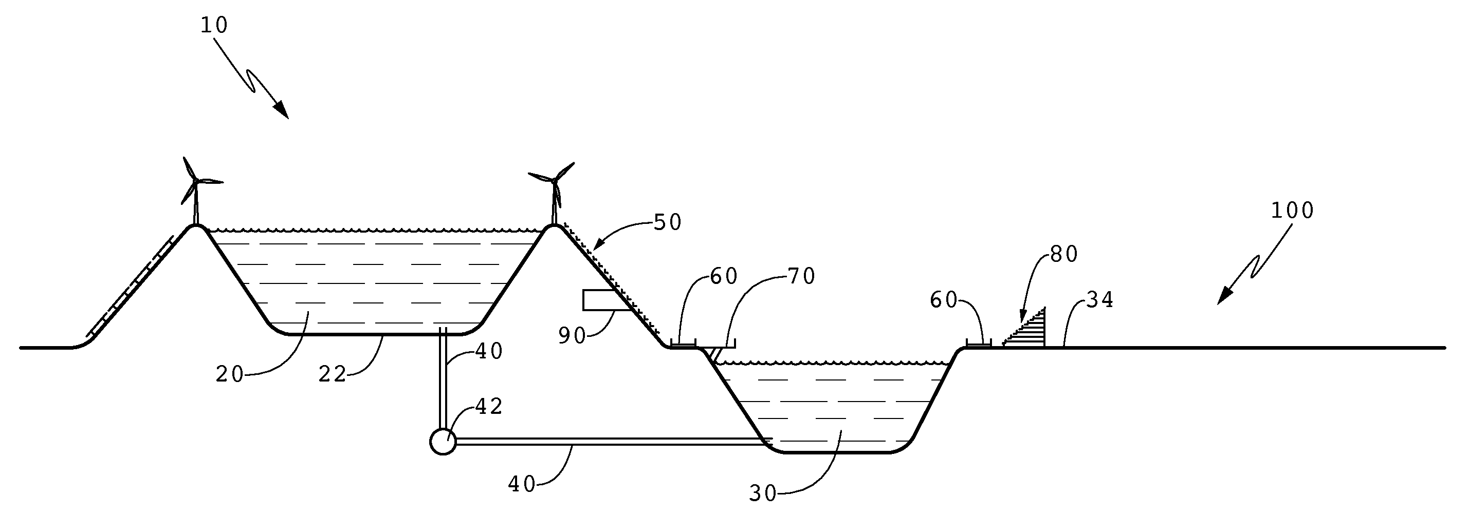
[0021]FIG. 1 shows a preferred pumped storage facility 10 having a first reservoir, such as the upper pond 20, and a second reservoir, such as the lower pond 30. While the terms “reservoir” and “pond” are used herein, any large container of water similar to a pond, reservoir, lake, sea or any other body of water can be considered equivalent. The upper pond 20 and the lower pond 30 are located at different elevations from one another such that water flowing from the upper pond 20 tends to flow downward toward the level of the lower pond 30 under the force of gravity alone. Similarly, water flowing out of the lower pond 30 does not tend to flow toward the upper pond 20 under the force of gravity alone.

[0022]A conduit 40 connects the upper pond 20 to the lower pond 30. In a preferred embodiment, the conduit 40 is a large pipe that is many feet in diameter, and the pipe can be made of any material, including without limitation, steel, plastic or concrete. Water in the upper pond 20 can ...


PUM


Abstract

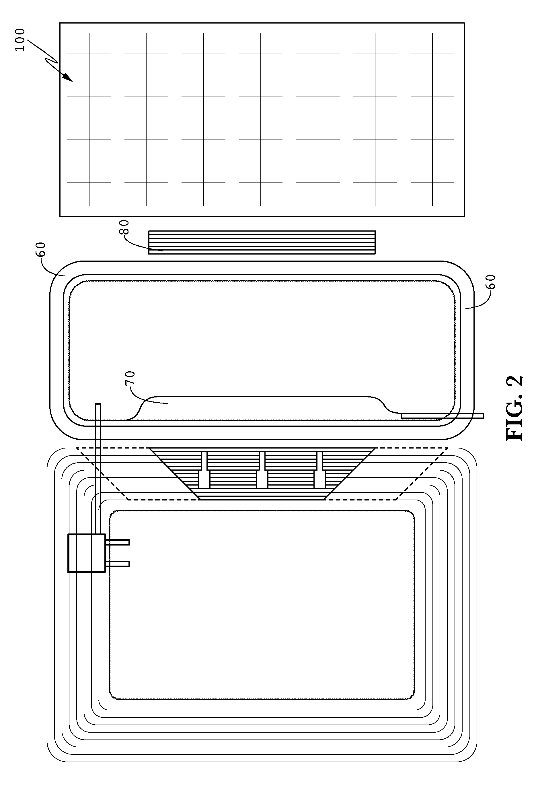
A pumped storage facility combined with at least a seating area constructed on a bank of an upper reservoir facing a lower reservoir. The lower reservoir includes a track around the shore thereof so that spectators in the seating area can view the track. A performance area is constructed adjacent the track along the lower reservoir, and can be built over the water on piers if needed. Thus, racing events can take place on the track and be viewed by spectators in the seating area. A parking lot drains water into the lower reservoir.

Description

BACKGROUND OF THE INVENTION[0001]The invention relates generally to a pumped storage facility, and more specifically to a pumped storage facility that includes other features that cooperate with the pumped storage facility to make it economically feasible to construct and operate the facility.[0002]The availability of power when needed is a major drawback to the production and use of any form of energy, but particularly alternative energy. The requirement that one match the inconsistent availability of alternative energy-produced power with production from a standard power plant, or Guaranteed Source of Power (“GSOP”), is also a disadvantage. A GSOP is typically a coal-burning power plant, nuclear energy plant, natural gas burning plant, or any other conventional energy-producing source of power.[0003]If the wind is blowing or the sun is shining, alternative power is available if one has windmills or photovoltaic cells in operation. However, if the blowing wind or the shining sun st...

Claims


Application Information

Patent Timeline
Patent Type & Authority Patents(United States)
IPC IPC(8): E02B9/02F03B13/06
CPCF03B13/06E02B9/02Y02E60/17Y02E10/22E02B9/00E04H3/12Y02E10/20Y02E60/16
Inventor IGEL, V, GEORGE J.
Owner WINDMARKET
Learn More